Maintenance instructions, Figure 7 figure 6 – Hydrotech ProFlo SXT Valve Downflow_Upflow Automatic Water Softeners Operation Manual User Manual
Page 13
Maintenance Instructions
Checking the Salt Level
Check the salt level monthly. Remove the lid from the cabinet or brine tank, make sure salt level is always above the
brine level (you should not be able to see water).
Adding Salt
Use only clean salt labeled for water conditioner use, such as crystal, pellet, nugget, button or solar. The use of rock salt
is discouraged because it contains insoluble silt and sand which build up in the brine tank and can cause problems with
the system’s operation.
Add the salt directly to the tank, filling no higher than the top of the brine well.
Caution
Liquid brine will irritate eyes, skin and open wounds - gently wash exposed area with fresh water. Keep children away
from your water conditioner.
Resin Cleaner
An approved resin cleaner must be used on a regular basis if your water supply contains iron. The amount of resin
cleaner and frequency of use is determined by the quantity of iron in your water (consult your local representative or
follow the directions on the resin cleaner package).
Care of Your Water Conditioner
To retain the attractive appearance of your new water conditioner, clean occasionally with a mild soap solution. Do no
use abrasive cleaners, ammonia or solvents. Never subject your conditioner to freezing.
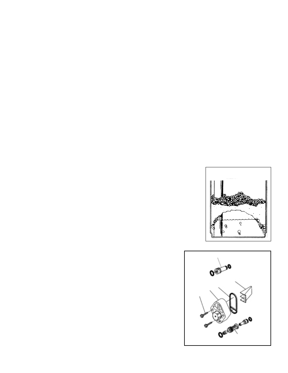
Bridging (Figure 6)
Humidity or the wrong type of salt may create a cavity between the water and the salt.
This action, known as “bridging”, prevents the brine solution from being made, leading to
your water supply being hard.
If you suspect salt bridging, carefully pound on the outside of the plastic brine tank or
pour some warm water over the salt to break up the bridge. This should always be
followed up by allowing the unit to use up any remaining salt and then thoroughly
cleaning out the brine tank. Allow four hours to produce a brine solution, then manually
regenerate the softener.
Cleaning the Injector Assembly (Figure 7)
Sediment, salt and silt will restrict or clog the injector. A clean water supply and pure salt
will prevent this from happening.
The injector assembly is located on the left side of the control valve. This assembly is
easy to clean.
Shut off the water supply to your softener and reduce the pressure by
opening a cold soft water faucet. Using a screwdriver, remove the two screws
holding the injector cover to the control valve body. Carefully remove the
assembly and disassemble as shown in Figure 7. The injector orifice is
removed from the valve body by carefully turning it out with a screwdriver.
Remove the injector throat the same way. Carefully flush all parts including
the screen. Use a mild acid such as vinegar or Pro-Rust Out to clean the
small holes in the orifice and throat.
Reassemble using the reverse procedure.
NOTE: The injector cover contains a factory set pressure regulator. Do not
attempt to adjust this regulator.
11
Injector Plug
Injector Throat/
Nozzle Assembly
Screen
O-ring
Screws
Injector
Cover
Figure 7
Figure 6