Braukman air vent installation – Hydrotech 2510 Valve Chemical Free Iron Filter Operation Manual User Manual
Page 7
6. Position drain hose over drain and secure firmly. To prevent back-siphoning of sewer water, provide an air gap to
code or equivalent (Fig 5). Do not raise drain hose more than 10 ft. above floor.
7. Turn on power to well pump. Be sure that the filter control is on the backwash position then disconnect power supply.
Fill the unit with water slowly by cracking open main supply valve. After all air is out of the unit and only water is run-
ning to the drain, fully open the main supply valve. Let the unit backwash for a period of 10 minutes or until running
clear and free of fines then reconnect to power supply. Let the unit finish off its cycle automatically.
NOTE: During the initial backwashings, a small amount of fine white media may be observed in drain water. This is
normal.
8.
Set Hydro-Charger by following these steps:
A. Open nearest faucet until pump starts, then close faucet.
B. Place a finger over suction port (See Figure 7). A slight suction should be detected for a minimum of 20 seconds
or for approximately one-third of pumping cycle whichever is greater.
C. If suction duration is too short, increase by turning water flow adjusting screw (Figure 7) clockwise. To decrease
duration, turn counterclockwise.
D. Repeat Steps A through C until proper setting is obtained. NOTE: When the
duration of the suction is too long, cold water may have a “milky” appearance
caused by excess air in system. Correct this condition by reducing the duration
of suction. This condition is one commonly associated with bladder-type pres-
sure tanks. In extreme cases excess air prevents the system from performing
satisfactorily, consequently it is essential to install an air relief valve (such as a
Braukman) in the proper location.
9
Make certain bypass is closed and inlet and outlet valves are fully opened. Check
for leaks.
10. Set time-of-day and backwash frequency (see Sec.5: Programming Backwash
Controls).
7
WATER FLOW ADJUST-
ING SCREW
SUCTION PORT
FIGURE 7
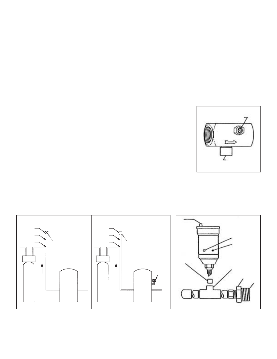
1. Air Release Cap must be loose or removed to allow air to escape from vent.
2. Vent Bushing 1/2” x 1/8”
3. To opening on side of retention tank (approximately 1/2 way up, from bottom of tank)
4. 3/4” x 3/4” x 1/2” copper tee
5. 3/4” adapter with bushing to tank
Braukman Air Vent Installation
The Braukman Air Vent must be installed at the highest point of the plumbing, between the pressure tank and filter (see Fig. 8).
Please note that the Braukman Air Vent (A) is mounted on a four to six inch pipe extension (B) at the elbow (C) of the highest
point. This enables the vent to better collect any excess air created by the hydrocharger.
To use the Braukman Air Vent on an air-to-water pressure tank, install it approximately halfway up the side of the tank, as shown
in the detailed drawing below.
OPEN
CLOSED
1
2
4
3
FIGURE 8A
FIGURE 8B
A
Braukman
Air Vent
Braukman
Air Vent
Pressure
Tank
(Diaphragm)
Pressure
Tank
(Air to Water)
See
Figure
9
B
C
A
B
C
Out
In
Out
In
5
FIGURE 9