Installation – Hydrotech 2510 Valve Chemical Free Iron Filter Operation Manual User Manual
Page 6
6
Installation
NOTE: Before starting installation, read Sec. 4, Plumbing System Cleanup, for instructions on some procedures that
may need to be performed first.
1. Shut off all water at main supply. On a private well system turn off power to pump and drain pressure tank. Make cer-
tain pressure is relieved from complete system by opening nearest faucet to drain system. Shut off fuel supply to
water heater.
Media Installation (When Necessary)
•
Remove the valve from the mineral tank.
•
Temporarily plug the open end of the riser tube to ensure that no resin or gravel falls down into the distribution.
•
Fill mineral tank one quarter full of water to protect distribution during gravel installation.
•
Slowly and carefully add the gravel support bed and the softener or filtration media leveling each layer as it is placed
into the tank.
•
Unplug the riser tube, carefully position the valve over it and turn the valve into the threads in the fiberglass tank,
tightening securely into tank. Note: Ensure that the internal O-ring
in the valve fits securely over the riser tube. Silicone grease
(#13691) or other food grade lubricant may be applied to the O-ring
to ease installation of the riser tube. DO NOT use petroleum based
lubricants as they will cause swelling of O-ring seals.
•
The softener or filter is now charged with softening resin.
•
It is recommended that the softener or filter tank now be completely
filled with water (SLOWLY) to soak the resin or filtration media
before startup. This will allow the media to absorb water as well as
help displace any trapped air. This will reduce the chance of back-
washing resin or filter media out of the tank during the initial back-
wash on startup.
2. Cut main supply line as required to fit hydro-charger in plumbing
between well pump and pressure tank (hydro-charger may be
installed in a vertical or horizontal position). Allow a minimum of 6
in. straight run of pipe on each side of hydro-charger, excluding fit-
tings. Polybutylene pipe is recommended between the hydro-
charger and pressure tank to reduce build-up and easier disman-
tling for service. Be certain direction of flow arrow on hydro-charger
points toward pressure tank, and pressure control switch is located
on pressure tank side of the hydro-charger as in Figs. 1, 2 or 3
(rapid cycling of pump may occur if pressure switch is located on
well side. If check valves are used they should be installed before
the Hydro-Charger - not between the Hydro-Charger and pressure
tank).
NOTE: It is advisable to install the hydro-charger with unions at
both ends to facilitate removal and inspection. If heat is applied
near Hydro-Charger, remove rubber check valve to prevent damag-
ing it. On badly scaled older pumping systems, it may be advanta-
geous to install an optional “WYE”-strainer ahead of Hydro-Charger
to prevent plugging Hydro-Charger nozzle with scale.
3. Cut main supply line as required to fit plumbing to control valve and
attach the single lever bypass valve (Fig. 4).
4. Solder or solvent weld plumbing. Do not apply heat to any fitting
connected to control valve as damage may result in internal parts.
Check to be certain water supply pipe is connected to control valve
inlet fitting, and pipe connected to control valve outlet fitting is in
direction of house service (see Fig. 5). NOTE: If the installation to be split-streamed prior to the filter tank (Fig. 2), or
is a public water supply type installation (Fig. 3), refer to special instructions following Step 11.
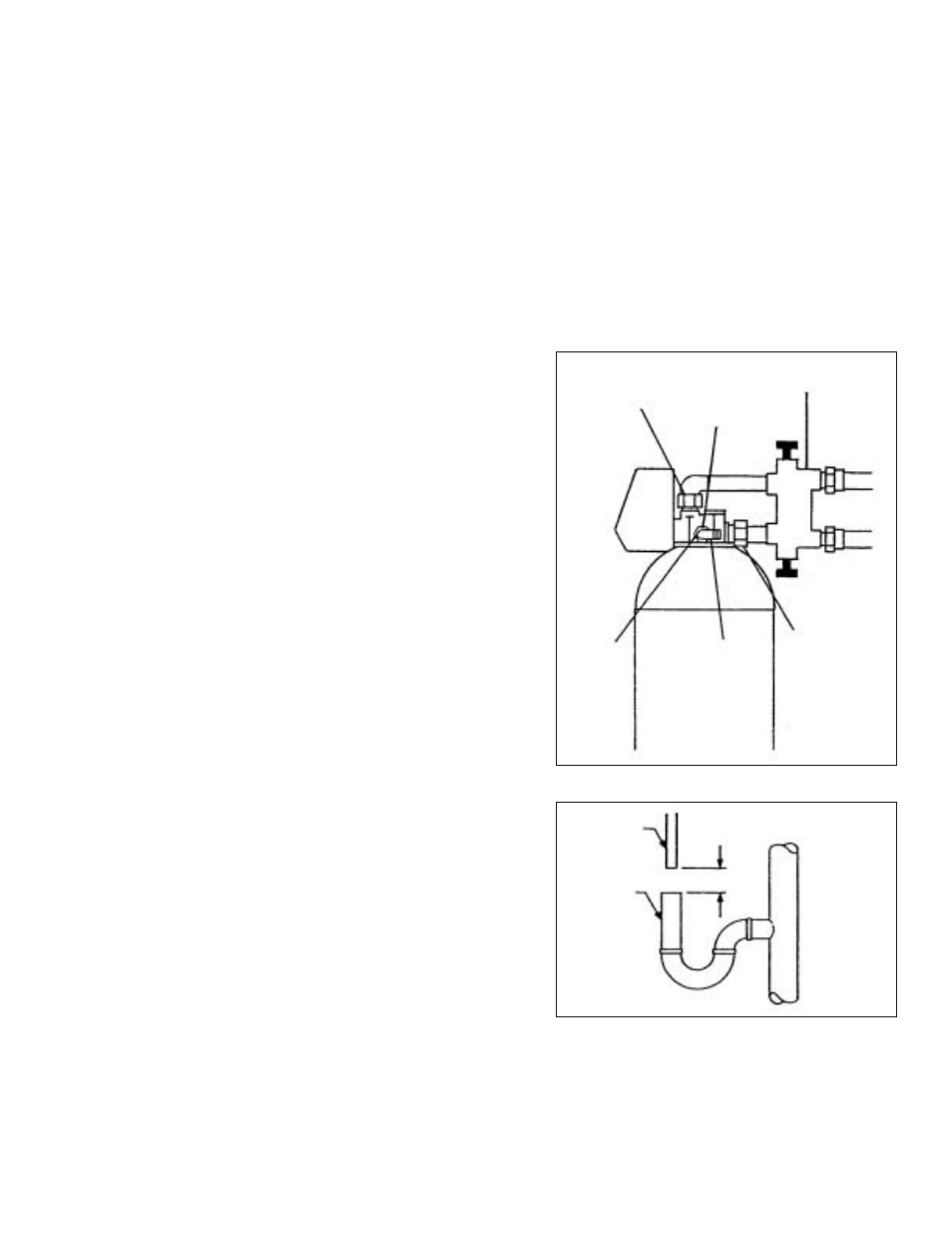
5. Loosen set screw and pull out drain line flow control assembly from valve body. Unscrew drain line fitting elbow from
drain line flow control. Apply pipe dope or teflon tape to threads. Reassemble to valve body, making certain drain line
flow control assembly is fully inserted into valve body before tightening set-screw. Attach 1/2 in. ID drain line to drain
elbow. Caution: Set-screw requires only finger pressure to hold plastic flow control in place. Over-tightening set-screw
may crack fitting.
FIGURE 4
FIGURE 5
OUTLET
SET
SCREW
BYPASS VALVE
INLET
DRAINLINE
ELBOW
FLOW CON-
TROL
ASSEMBLY
EQUIPMENT
DRAIN LINE
AIR GAP
DRAIN
2”