Hydrotech SL948-10-5600 Residential Scaleless System User Manual
Page 5
Cold Treated
Hot Treated
Water Filter
4
• Slowly and carefully add the gravel support bed and the filter or filtration media leveling each layer as it is placed into
the tank.
• Unplug the riser tube, carefully position the valve over it and turn the valve into the threads in the fiberglass tank,
tightening securely into tank. Note: Ensure that the internal O-ring in the valve fits securely over the riser tube.
Silicone grease (#13691) or other food grade lubricant may be applied to the O-ring to ease installation of the riser
tube. DO NOT use petroleum based lubricants as they will cause swelling of O-ring seals.
• The filter is now charged with filter media.
• It is recommended that the filter tank now be completely filled with water (SLOWLY) to soak the resin or filtration
media before startup. This will allow the media to absorb water as well as help displace any trapped air. This will
reduce the chance of backwashing resin or filter media out of the tank during the initial backwash on startup.
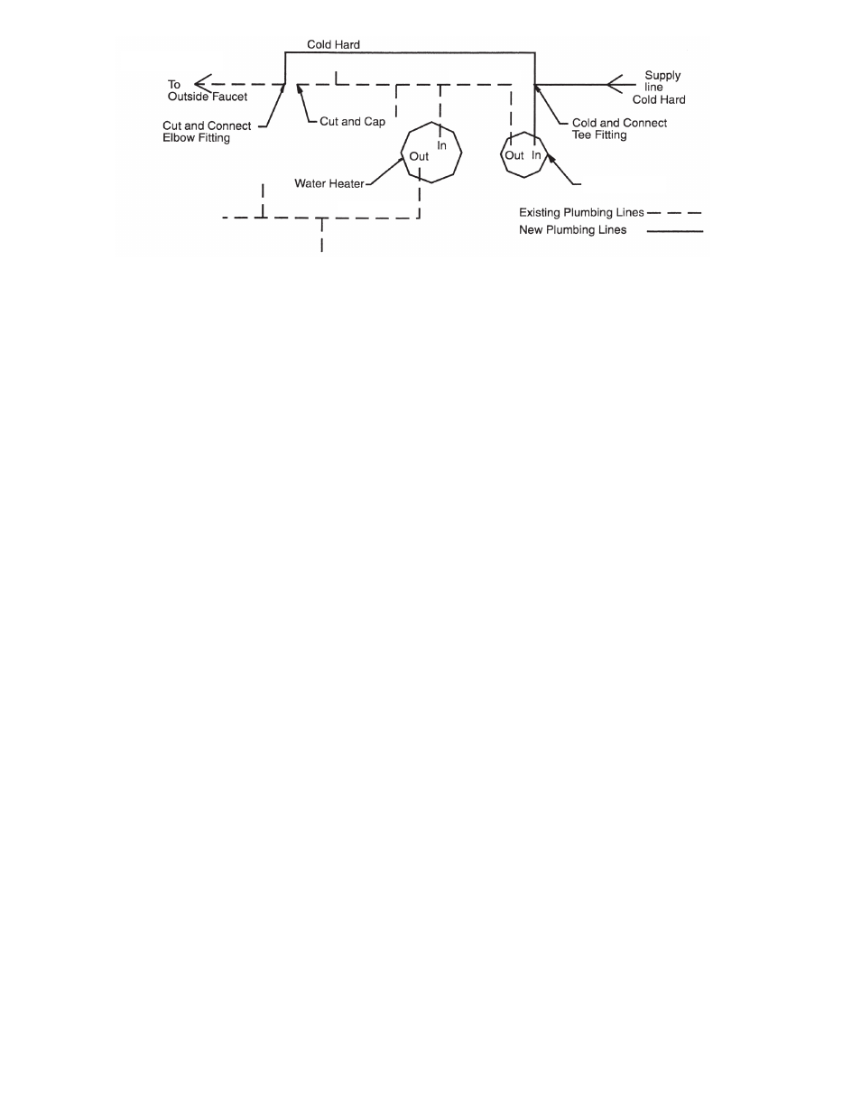
2. Outside faucets used to water lawns and gardens should not supply treated water. A new water line is often required
to be connected to supply hard water to the inlet of the water filter and to the outside faucets. Cut the water line
between where it enters the house and before any lines that branch off to feed the hot water heater or other fixtures
in the house and as near the desired location of the water filter as possible. Install a tee fitting on the feed end of the
cut pipe, and an elbow fitting on the other end. Install piping from the tee to the inlet of the water filter and from the
elbow to the outlet of the filter. To sever the water lines which branch off to feed any outside faucets, cut the branch
lines approximately two inches from the fitting on the main water line. Install an elbow on the end of the pipe nearest
the outside faucet and a cap on the end connected to the existing water line. Install piping from the tee installed on
the inlet line to the water filter to the elbow installed on the pipe to the outside faucet. Following this procedure will
result in all lines in the house, with the exception of the outside faucets, but including the water heater and therefore
the hot water lines, being supplied with filter water.
3. Familiarize yourself with the location of the inlet, outlet and drain on the control valve. Be very careful not to get the
controls wet.
4. Attach the bypass valve to the control valve. Connect the inlet and outlet of the water filter to the plumbing in the
house. The control valve must not be submitted to temperatures above 43°C (110°F). When sweat fittings are used,
to avoid damaging the control valve, solder the threaded copper adapters to the copper pipe and then, using Teflon
tape, screw the assembly into the bypass valve.
CAUTION - do not use pipe thread compound as it may attack the material in the valve body.
5. Using teflon tape, screw the 1/2” hose barb into the drain port in the valve. Attach 1/2” drain hose to the hose
barb and tighten securely with a hose clamp. Run the drain line to a floor drain or a laundry drain. Complete any
necessary plumbing.
6. Make sure the bypass valve is in the service position.
7. Plug the 24-volt transformer into a 120 VAC 60 Hz outlet. This valve has four positions: 1) Backwash and
2) Rapid Rinse. When the valve is in the Service position, the extra cycle button (far left button as shown on Figure
4) must be pressed and held for 5 seconds before it activates. Press and hold the extra cycle button for 5 seconds
to advance the valve into the “1” Backwash position. Slowly turn on the water supply and allow the unit to backwash
until the air purges out of the tank and clears the system.
8. Press the extra cycle button to advance the valve to the “3” Rapid Rinse position and allow water to run to drain for 2
minutes.
ALL STATE AND LOCAL GOVERNMENT CODES GOVERNING INSTALLATION OF THESE DEVICES MUST BE OBSERVED.
Figure 3