Hellwig Sway Bar 7898 User Manual
Page 2
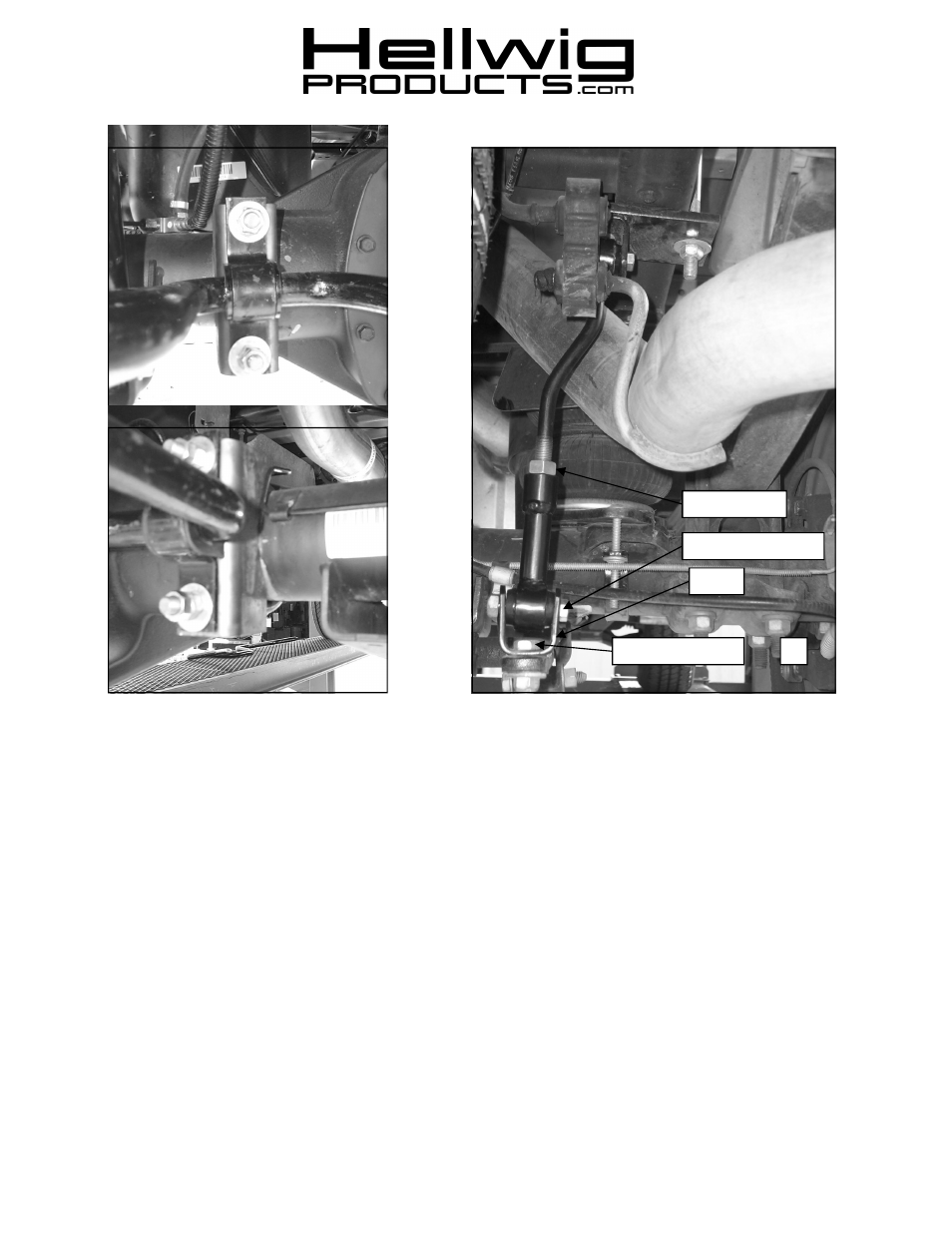
7.
Assemble end links as shown in photos with 9/16” nut on the threaded half. Leave loose for adjustment. Insert hourglass bushing first
and then sleeve into the loops of the end link assembly.
Lubricate the bushing and sleeve to ease assembly
8.
Attach clevis on sway bar to end link using 7/16 X 2-1/4” bolts and locknuts provided in kit.
LEAVE LOOSE AT THIS TIME to allow
for adjustment later.
9.
With sway bar loosely mounted, work bar back and forth in D-shaped poly bushings to center bar.
10.
Tighten frame bracket U-bolts to 50 ft-lb..
11.
Tighten end link clevis bolts to 35 ft-lb.
12.
Tighten jam nut on end link to lock into place.
13.
Tighten axle U-bolts to 60 ft-lb. Place second nut on U-bolt and tighten against primary nut to lock in place.
14.
Recheck your installation, looking for clearance on any undercarriage components, such as gas lines, exhaust pipes, brake lines, wiring,
differential cover, etc.
15.
Drive vehicle for a few miles, then recheck for position and tightness, readjust and retorque as needed. Then recheck periodically
thereafter.
ATTENTION INSTALLER: PLEASE MAKE SURE CUSTOMER RECEIVES THIS INSTRUCTION SHEET,
7895(R-7895)
02/17/09
559-734-7451 800-367-5480 FAX 559-734-7460
3
Clevis
9/16” Jam Nut
7/16 X 2-1/4” Bolt
1/2 X 1-1/2” Bolt