Hellwig Sway Bar 7899 User Manual
Page 2
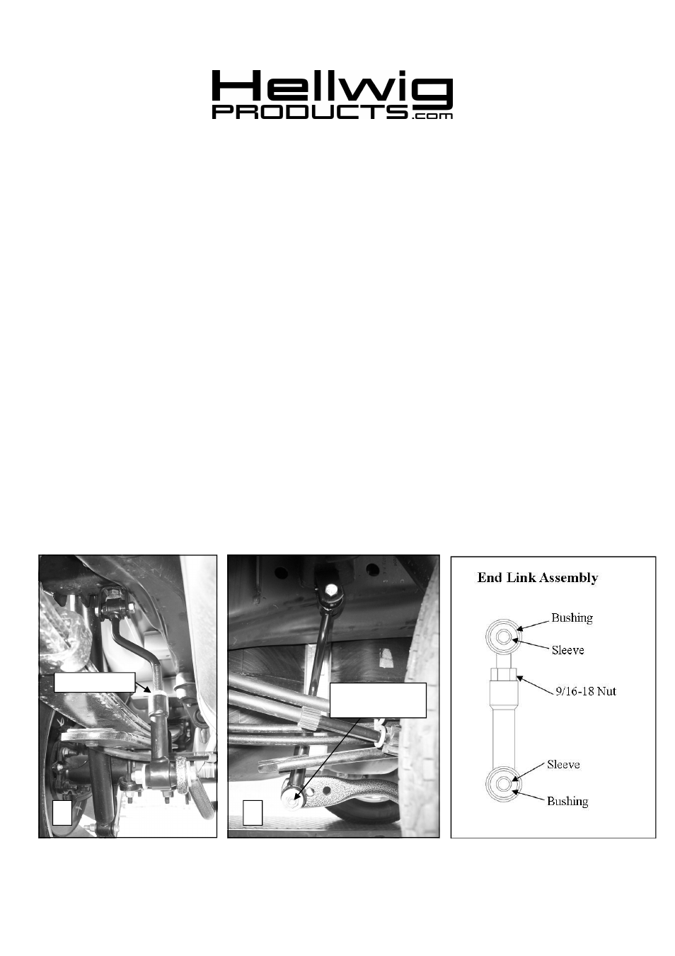
1. Install the Threaded Plates inside the rear shock crossmember as shown in Photo 2.
2. Attach clevis to threaded plate using the 1/2-20 X 1” bolts provided as shown in Photo 3. Align clevis as
shown in photo and torque bolt to 40 ft-lb.
3. Insert hourglass bushings into the loops of the end links. Lubricate bushings with supplied lubricant to aid
installations. Install sleeves into hourglass bushings.
4. Assemble end links together as shown in photo 4 with 9/16” jam nut on threaded portion of end link. Leave
loose for adjustment later.
5. Loosely attach end links to clevis using 7/16-20 X 2-1/4” bolt and locknut as shown in photo 4.
Leave loose
for adjustment later.
6. Prepare axle to attach sway bar by unclipping brake line from tab on axle as shown in photo 7.
Install U-
bolts over axle as shown in photos 6&7. Make sure that the U-bolts are under any brake lines, wires
or hoses on the axle to avoid pinching or crushing when the U-bolts are tightened.
SAFETY:
BEFORE STARTING YOUR INSTALLATION, BE SURE TO SET PARKING BRAKE AND CHOCK TIRES.
NOTE:
TO EASE INSTALLATION AND TO PROPERLY ADJUST THE BAR, THE WEIGHT OF THE VEHICLE MUST BE
ON THE SUSPENSION, AS IF DRIVING DOWN THE ROAD.
DO NOT RAISE VEHICLE BY THE FRAME.
NOTE:
THIS SWAY BAR IS DESIGNED TO MOUNT ON THE REAR OF THE DIFFERENTIAL WITH THE ARMS TO
WARDS THE FRONT OF THE VEHICLE.
NOTE:
THIS KIT INCLUDES LOCK NUTS WHICH REQUIRES TIGHTENING WITH A WRENCH AFTER BEING
STARTED BY HAND.
TORQUE TABLE
BOLT SIZE: 3/8” = 20-30 ft. lbs. – 7/16” = 35-45 ft. lbs. – ½” = 50-70 ft. lbs. – 9/16” = 70-90 ft. lbs.-5/8”=120 ft. lbs.
559-734-7451 800-367-5480 FAX 559-734-7460
9/16” Jam Nut
4
5
7705 ( R-7705 )
11/17/2009
Attach end link to
this hole