Hellwig Sway Bar 7707 User Manual
Page 2
7701 (R-7701)
08/22/2008
TORQUE TABLE
BOLT SIZE: 3/8” = 20-30 ft. lbs. – 7/16” = 35-45 ft. lbs. – ½” = 50-70 ft. lbs. – 9/16” = 70-90 ft. lbs.
SAFETY:
BEFORE STARTING YOUR INSTALLATION, BE SURE TO SET PARKING BRAKE AND CHOCK TIRES.
NOTE:
TO EASE INSTALLATION AND TO PROPERLY ADJUST BAR, THE WEIGHT OF THE VEHICLE MUST BE ON THE SUS-
PENSION, AS IF DRIVING DOWN THE ROAD.
DO NOT RAISE VEHICLE BY FRAME.
NOTE:
THIS UNIT IS DESIGNED TO REPLACE THE FACTORY INSTALLED REAR ANTI-SWAY BAR. THE HARDWARE CON-
NECTING THE BAR TO THE AXLE AND THE END LINKS TO THE FRAME WILL HAVE TO BE REUSED.
NOTE:
THIS KIT INCLUDES LOCK NUTS WHICH REQUIRE TIGHTENING WITH A WRENCH AFTER BEING STARTED BY HAND.
1. Remove the factory installed rear anti-sway bar and all the mounting hardware.
2. As per the photos, lubricate and install the D-shaped poly bushings onto the bar in the same location as the
factory installed bushings on the sway bar. Place the U-plates over the D-bushings and attach the bar to the
axle using the mounting hardware removed in step number one (1),
Leave loose at this time to allow for
adjustment later. Use supplied grease to lubricate D-bushings.
3. As per the diagram, assemble the adjustable end links. Use supplied grease to lubricate the hourglass bush-
ings and sleeves before assembly.
Insert hourglass bushing into end link loop first and then insert the
sleeve. The 3/4” diameter sleeve is used at the top of the end links to attach to the frame bracket.
4. Attach the end links to the frame bracket using the 1/2” bolt, washers, and locknut as shown in photos.
Torque to 50-60 ft-lb.
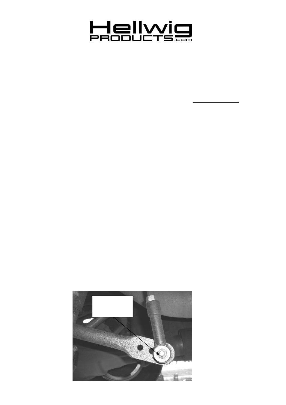
5. Attach the end links to the outermost hole in the sway bar using the 7/16”X 2-3/4” bolt, washers, and lock
nut as shown in photos. Torque to 30-35 ft-lb.
6. Center the sway bar under the vehicle by moving the bar side to side. Adjust the end links so that the sway
bar is as level with the frame as possible.
7. Tighten axle bolts to 20-25 ft-lb.
8. The sway bar arms have three mounting holes. Mounting the sway bar on the outer hole is the nominal po-
sition. For firmer settings, use the inner holes. We recommend starting with the outer mounting hole until
you are accustomed to the vehicle’s new handling characteristics. Then select the mounting point that best
fits your driving style
9. Bounce the vehicle checking for clearance on all undercarriage components. Readjust the bar as needed and
check periodically on a regular basis thereafter.
ATTENTION INSTALLER:
BE SURE THAT THE CUSTOMER RECEIVES THIS INSTRUCTION SHEET,
ALL IMORTANT NOTE CARDS AND THE WARRANTY FORM
559-734-7451 800-367-5480 FAX 559-734-7460
Attach end link to
end hole for initial
adjustment.