Hellwig Sway Bar 7694 User Manual
Page 3
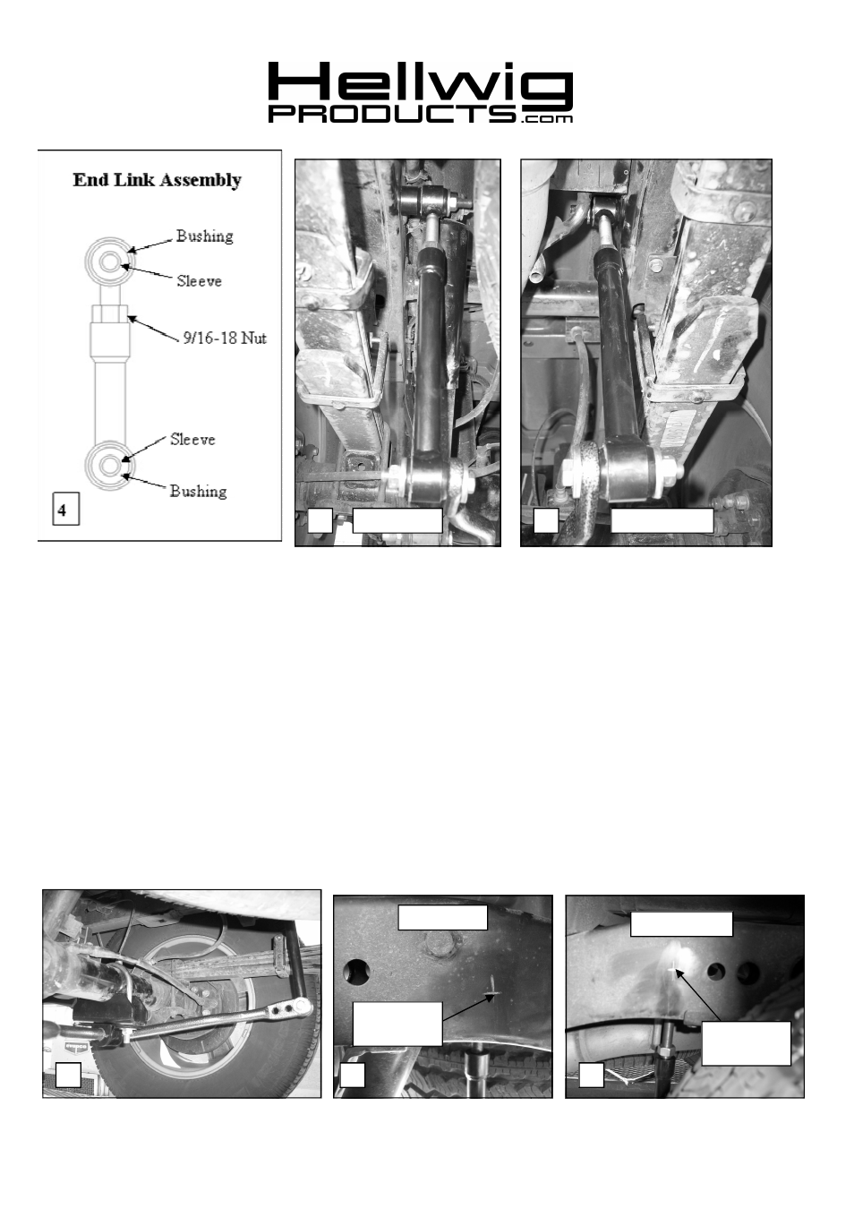
5. Assemble end link assembly by inserting hourglass bushings into loops in end links first. Then insert
sleeves into bushings. Lubricate bushings and sleeves with supplied grease before assembly.
6. Attach end links to the outer hole of the sway bar and align end links for best fit as shown in PHOTO 4.
7. Attach end link to outermost hole in sway bar using 7/16 X 2-3/4 bolt, thick washers and locknut as
shown in photos 1 & 7. Torque bolt to 40 ft-lb.
8. Align end links for best fit as shown in PHOTOS 1,5,6,&7. Note that a 3/4” spacer is used on the driver
side only as shown in PHOTO 5.When satisfied with their location, mark location of holes for the end
links as shown in PHOTOS 8 & 9.
9. Transfer hole location to outer edge of subframe rail. A piece of card board can be used by marking the
location of the hole on the cardboard and transferring the location to the outer rail. Drawing a line on
the subframe square to the subframe rails will keep the hole location square. See PHOTOS 8&9.
10.
Review end link mounting detail before drilling holes. BEFORE DRILLING ANY HOLES IN
THE RAIL—RELOCATE AND PROTECT ANY FUEL OR BRAKE LINES THAT MAY IN-
TERFERE WITH THE DRILL BIT OR SWAY BAR INSTALLATION.
559-734-7451 800-367-5480 FAX 559-734-7460
5
Driver Side
Passenger Side
6
Passenger Side
Driver Side
7
8
9
Center of end
link bushing
Center of end
link bushing
7694 (R-7694)
08/22/2007