Hellwig Sway Bar 7270 User Manual
Page 3
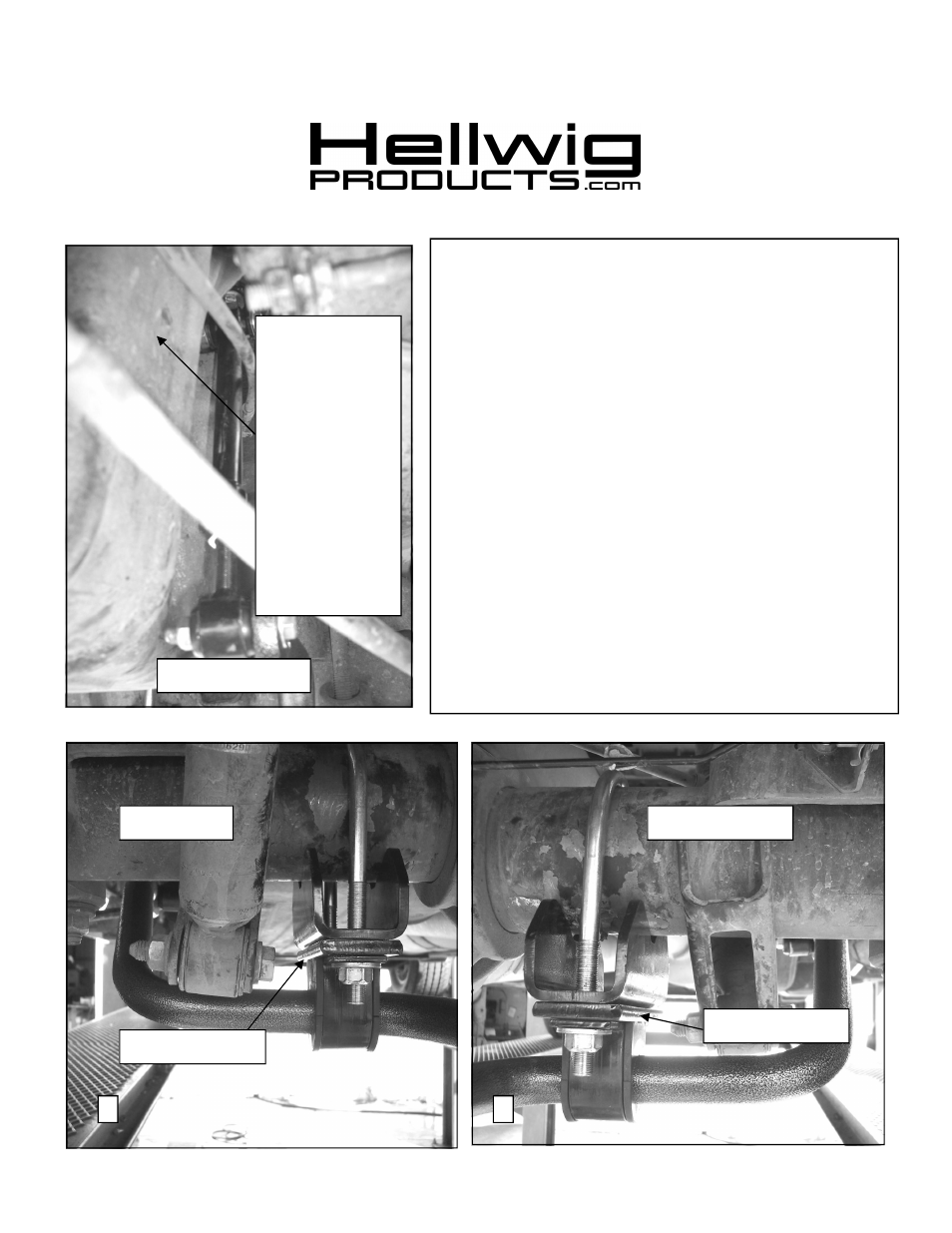
1. Locate large slotted hole in side of frame rails approximately
12” forward of the bump stops as shown in photo 1.
2. Insert threaded plate into large slotted hole and use wire pig-
tail to orient threaded plate to slotted hole on bottom of frame
rail.
3. Attach clevis to threaded plate with 1/2 X 1-1/4” bolt as
shown in photo 2. Align clevis to be square with the frame
rail and torque bolts to 50 ft-lb.
4. Assemble end links as shown in photos 2&3 by inserting the
hourglass bushing first and then the sleeve into the loops of
the end links.
Lubricate the bushing and sleeve before as-
sembly. Attach 9/16 nut to threaded half of end link before
assembling end link halves.
5. Attach end links to clevis on frame brackets using 7/16 X 2-
1/4 bolts and locknuts.
LEAVE LOOSE for adjustment
later. On driver side the plastic fuel tank shield can be loos-
ened to provide additional clearance for assembly. Reinstall
shield after installation is complete.
6. Place U-bolts on axle as shown in photos 4&5.
Be sure to
put the U-Bolts Under Any Brake Lines, Wires or Hoses
on the Axle to Avoid Any Possible Damage. The threads of
the U-Bolts will point down.
Driver’s Side
559-734-7451 800-367-5480 FAX 559-734-7460
Driver Side
Passenger Side
Plastic fuel tank
shield can be re-
moved to provide
additional clear-
ance for installa-
tion of sway bar
and end link.
REINSTALL
SHIELD AF-
TER INSTAL-
LATION IS
COMPLETE.
Driver Side
4
5
Spacer Plate
Spacer Plate
7270 (R-7270)
05/26/2011