Hellwig Sway Bar 7269 User Manual
Installation instructions, Rear stabilizer bar 7269
TORQUE TABLE
Bolt Size 3/8”— 25 ft lbs * Bolt Size 7/16”— 35 ft lbs* Bolt Size 1/2”—60 ft lbs *
SAFETY
: BEFORE BEGINNING INSTALLATION BE SURE TO SET THE PARKING BRAKE
AND CHOCK THE WHEELS.
NOTE:
TO EASE INSTALLATION AND PROPERLY ADJUST THE BAR, THE WEIGHT OF THE
VEHICLE MUST BE ON THE SUSPENSION AS IF DRIVING DOWN THE ROAD. DO NOT RAISE
THE VEHICLE BY THE FRAME.
NOTE:
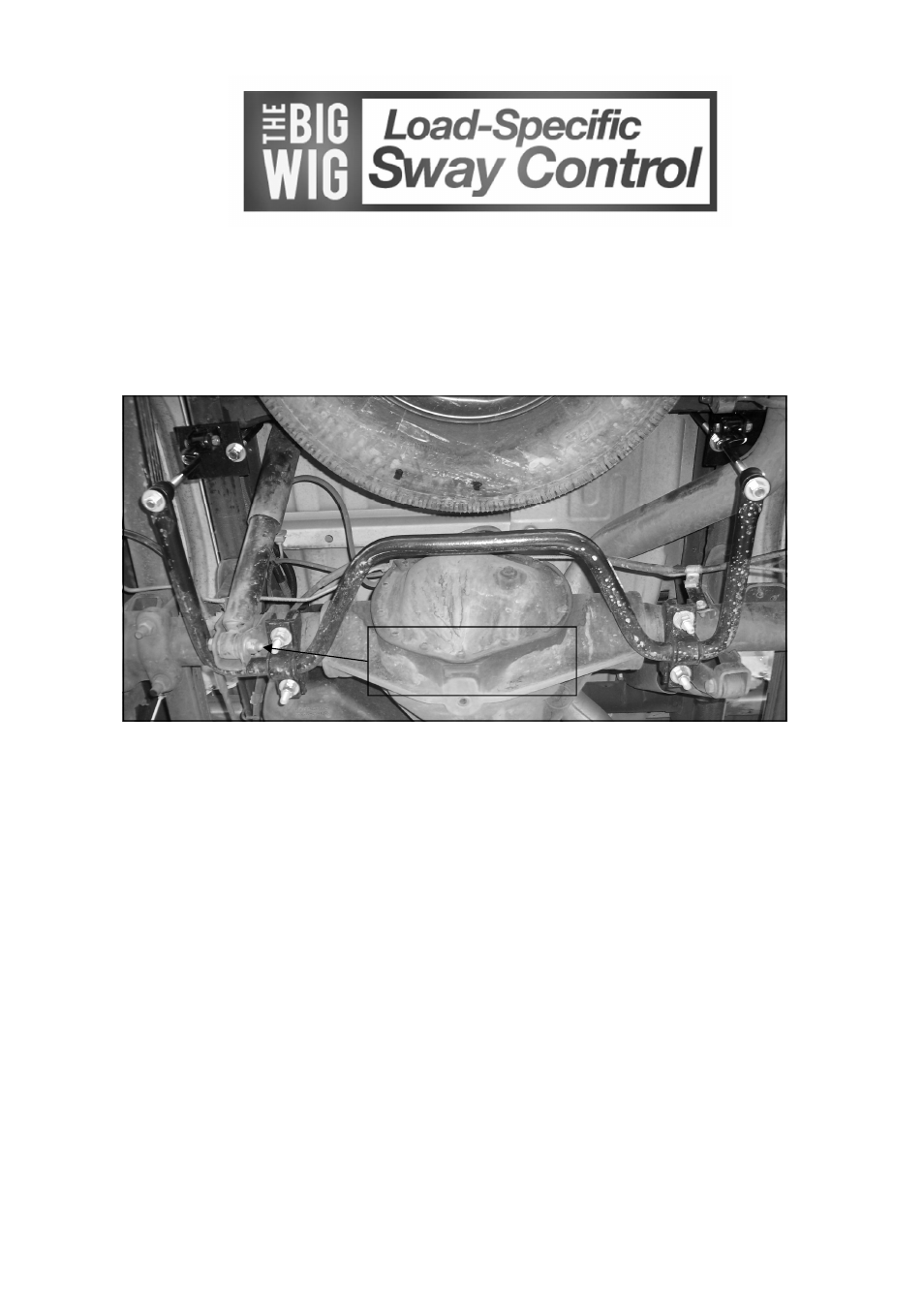
THIS UNIT IS DESIGNED TO MOUNT TO THE BOTTOM OF THE AXLE TUBES WITH
THE ARMS OF THE BAR TOWARD THE REAR OF THE VEHICLE.
1. Place the D shaped bushings onto the straight areas of the bar on each side of the center hump.
2. Hold bar up to the axle and locate the position on the axle tubes to mount the u-bolts.
Be sure to put the
U-Bolts Under Any Brake Lines, Wires or Hoses on the Axle to Avoid Any Possible Damage. The
threads of the U-Bolts will point down.
3. Remove brake cable/line bracket from axle and use single flat plate to relocate higher.
4. Place saddle brackets onto the U-Bolts on the axle tubes. The saddle brackets have different radius to ac-
commodate the taper in the axle tube. If they do not sit square, reverse their orientation. Place the U-Plates
over the D shaped bushings on the bar and attach the bar to the U-Bolts and saddle brackets with the flat wash-
ers and nuts provided.
LEAVE LOOSE AT THIS TIME to allow for adjustment later. For additional bar
clearance remove the driver side lower shock bolt, turn it around and reinstall from the opposite side of
the lower shock bracket.
INSTALLATION INSTRUCTIONS
Rear Stabilizer Bar 7269
2001-2006 GM 2500HD-3500HD 2WD-4WD
Thank you for purchasing a quality Hellwig Product.
PLEASE READ THIS INSTRUCTION SHEET COMPLETELY BEFORE STARTING YOUR INSTALLATION
Remove shock bolt and rein-
stall with bolt head facing out-
board for sway bar clearance.
7269 (R-7269)
11/19/2010