Hellwig Sway Bar 5818 User Manual
Page 3
3
4
5
3.
Place the saddle brackets onto the U-Bolts on the axle tubes. Place the U-Plates over the D shaped bushings on the bar and
attach the bar to the U-Bolts and saddle brackets with the flat washers and nuts provided.
LEAVE LOOSE AT THIS TIME
to allow for adjustment later.
6.
Position sway bar on axle so that it clears all frame mounted components including fuel tanks, brake lines, fuel lines, etc.
Sway bar can be rotated back and forth on axle to maximize clearance.
7.
Assemble end links by inserting bushings first and then inner sleeve into outer sleeve of end link.
Fully lubricate bushings
before installation. Install 9/16” nut on threaded section of end link before assembling the two halves together as shown.
IMPORTANT NOTE - The end link threads are NOT powder coated so that the end links can be threaded together.
To prevent corrosion, it is advised to lightly coat the exposed threads with black spray paint after adjusting to desired
length.
8.
Attach end links to the center hole of the sway bar and align end links for best fit as shown in PHOTO 2.
IMPORTANT
NOTE – Center hole position is only for determining hole location. The end link must be moved to the outer hole
prior to initial use
.
9.
The end links should be located as shown in PHOTO 2 so that the arms of the sway bar are parallel with the ground. When
satisfied with their location, mark location of holes for the end links.
10. Prepare to jack up vehicle by placing wheel chocks on the front wheels. After the rear of the vehicle has been raised,
sup-
port frame on jack stands and remove rear wheels.
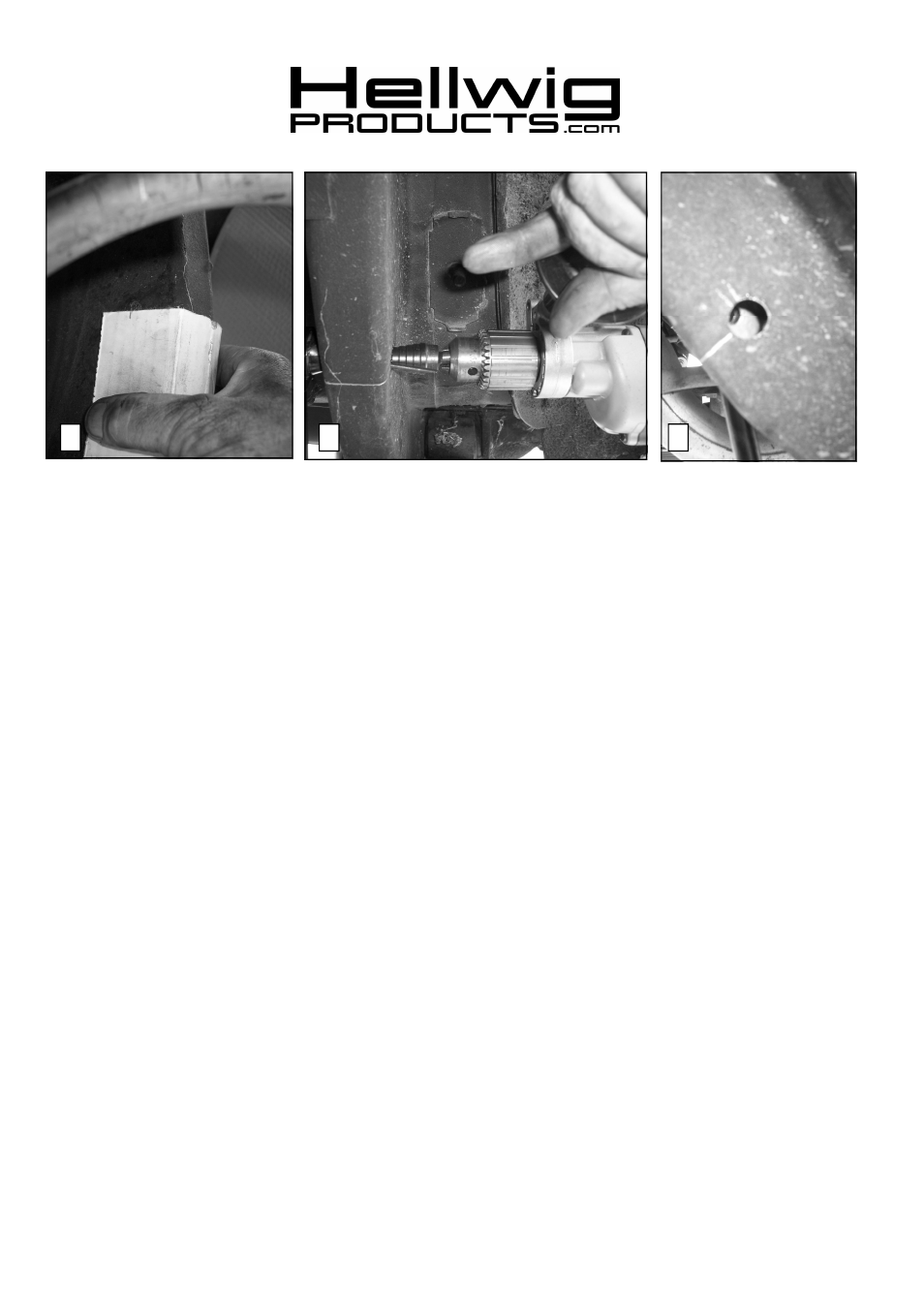
11. Transfer hole location to outer edge of subframe rail. A piece of card board can be used by marking the location of the hole
on the cardboard and transferring the location to the outer rail. Drawing a line on the subframe square to the subframe rails
will keep the hole location square. See PHOTO 3,4,&5.
12.
Review end link mounting detail before drilling holes. BEFORE DRILLING ANY HOLES IN THE RAIL—
RELOCATE AND PROTECT ANY FUEL OR BRAKE LINES THAT MAY INTERFERE WITH THE DRILL BIT
OR SWAY BAR INSTALLATION.
13. Drill a 15/32 (.468) hole through
BOTH walls of the subframe. Make sure holes are square to one another when drilling
holes.
14. Drill an 11/16 (.688) hole through
OUTER wall of subframe ONLY.
15. Insert 7/16 X 4-1/2 bolt through rail as shown in PHOTO 6. Insert spacer sleeve into hole so that it is flush with the inboard
wall of subframe. For severe duty it is recommended that the spacer tube be welded to the outer subframe wall.
If the
spacer is to be welded, review severe service end link detail on page 4 and skip to line 17. If any welding is to be done,
the installer must ensure that all hazards (fuel, electrical, etc) are eliminated and that fuel tanks, fuel lines, brake
lines, wiring, etc. are not affected by the welding operation.
16. Install Large washer over spacer tube and check that spacer tube is 1/32” (.031”) below the surface of large washer. Failure
to do this will result in insufficient preload and noise. File or grind end of spacer tube to achieve proper length. SEE
PHOTO 7.
17. Remove bolt and spacer and attach end link to subframe as shown in detail and PHOTO 8. Applications with welded spacer
do not require the washers on the outboard side of subframe. Torque end link bolts to 35-40 ft-lb.
18. Replace rear wheels and torque lug nuts to factory specification. Lower vehicle so that the full weight of the vehicle is on the
suspension.
19. Tighten axle u-bolts to 35 ft-lb.
559-734-7451 800-367-5480 FAX 559-734-7460
5818 (R-5818)
09/27/2008