Leveling valve installation diagram – Hellwig Compressor 4880 User Manual
Page 4
559-734-7451 800-367-5480 FAX 559-734-7460
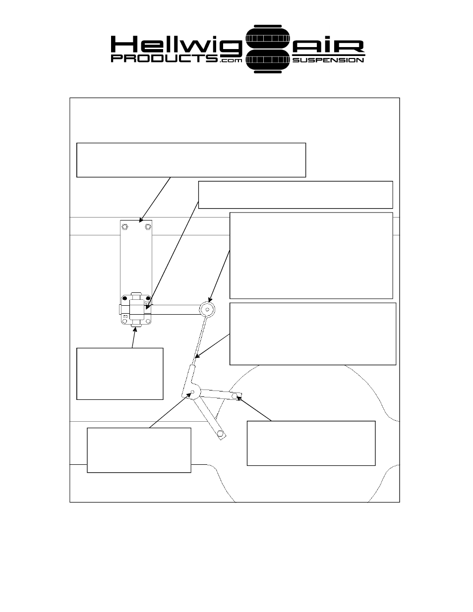
Leveling Valve Installation Diagram
Attach leveling valve mounting bracket to bed rail by drilling 3/8” dia.
holes and fastening with 5/16” bolts supplied. Locate valve so that the
valve and plumbing will not contact axle during use.
To set ride height, center leveling valve by inserting 11/64”
drill bit in hole in handle and body.
Adjust stud pins so that linkage is vertical when
viewed from side of vehicle. Adjust position of
valve and axle brackets so that linkage is positioned
as shown when viewed from rear of vehicle at de-
sired ride height. Secure adjustable end of linkage
with supplied hose clamp to lock height setting.
Attach axle brackets to axle using rear
cover bolts. Brackets are slotted to
accommodate various axles and to al-
low best placement of stud pin.
Attach axle brackets together
using stud pin. Orient stud pin
forward or rearward for best
orientation of linkage.
Remove drill bit and rotate arm up and down to
check for clearance to vehicle components. Meas-
ure axle bump stop clearance and add 1-1/2”. This
dimension represents how much clearance above
top of linkage is required for valve to clear bottom
of bed. With arm of valve centered. Measure the
distance from the top of linkage to the bottom of
bed. This distance must be greater than the bump
stop dimension obtained.
4880 ( R-4880)
03/09/07
Orient valve so that inlet/
exhaust ports are vertical.
Note: Base of inlet /
exhaust ports in valve
have a screen.