Hellwig Compressor 4885 User Manual
Page 6
559-734-7451 800-367-5480 FAX 559-734-7460
3. Follow plumbing and wiring diagram for connection of dash control, compressor, and
relay.
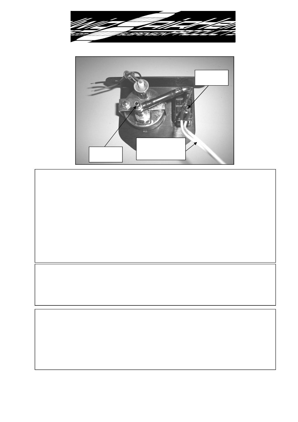
See photo above for connections to barbed fittings on dash control. Connect white
wires on back of switch as shown in plumbing and wiring diagram. Either white wire can
be the ground connection as long as the other wire is connected to the relay as shown in
the diagram. The supplied 1/4” nylon tube is designed to slip tightly over the barbed fit-
tings and will not require any additional clamps. If you need to remove a hose from the
barbed fitting, carefully cut the tubing so as not contact the fitting. If the fitting is dam-
aged or nicked a leak may develop. Take care when routing air and electrical lines that
they will not be crimped or chafed during installation or use. Deviation from the electrical
diagram and failure to use an inline fuse holder (supplied) will void warranty. DO NOT
install fuse in inline fuse holder until all connections and circuits are verified to be com-
pleted correctly.
4. After all connections have been verified, install fuse in inline fuse holder, apply park
brake and start engine with shifter in park or neutral. The compressor should turn on
when the dash switch is pushed up. Due to the amperage draw of the compressor, failure
to turn engine on during initial startup may drain the battery enough to require a jump
start.
5. Test system by adding air to air springs. Pushing up on the paddle switch will add air
to the system and pushing down will exhaust air.
Fill air springs to 40 psi and check all
connections with soapy water for leaks. After the integrity of the system is verified, the
air springs can be inflated to desired pressure.
A MINIMUM OF 5-10 PSI MUST BE
MAINTAINED IN AIR SPRINGS AFTER INSTALLATION FOR WARRANTY
TO BE VALID. FAILURE TO KEEP MINIMUM PRESSURE IN AIR SPRINGS
WILL VOID WARRANTY
.
4885 ( R-4885)
03/09/07
Connect to
Air Springs
Connect to
Compressor
Connect white wires
as shown in electrical
& plumbing diagram.