Generator installation, Igniting pilot burner, Control diagram – Green Air Products CO2 Generator User Manual
Page 2: Exhaust syncronized operation, Natural gas hook-up, Propane hook-up
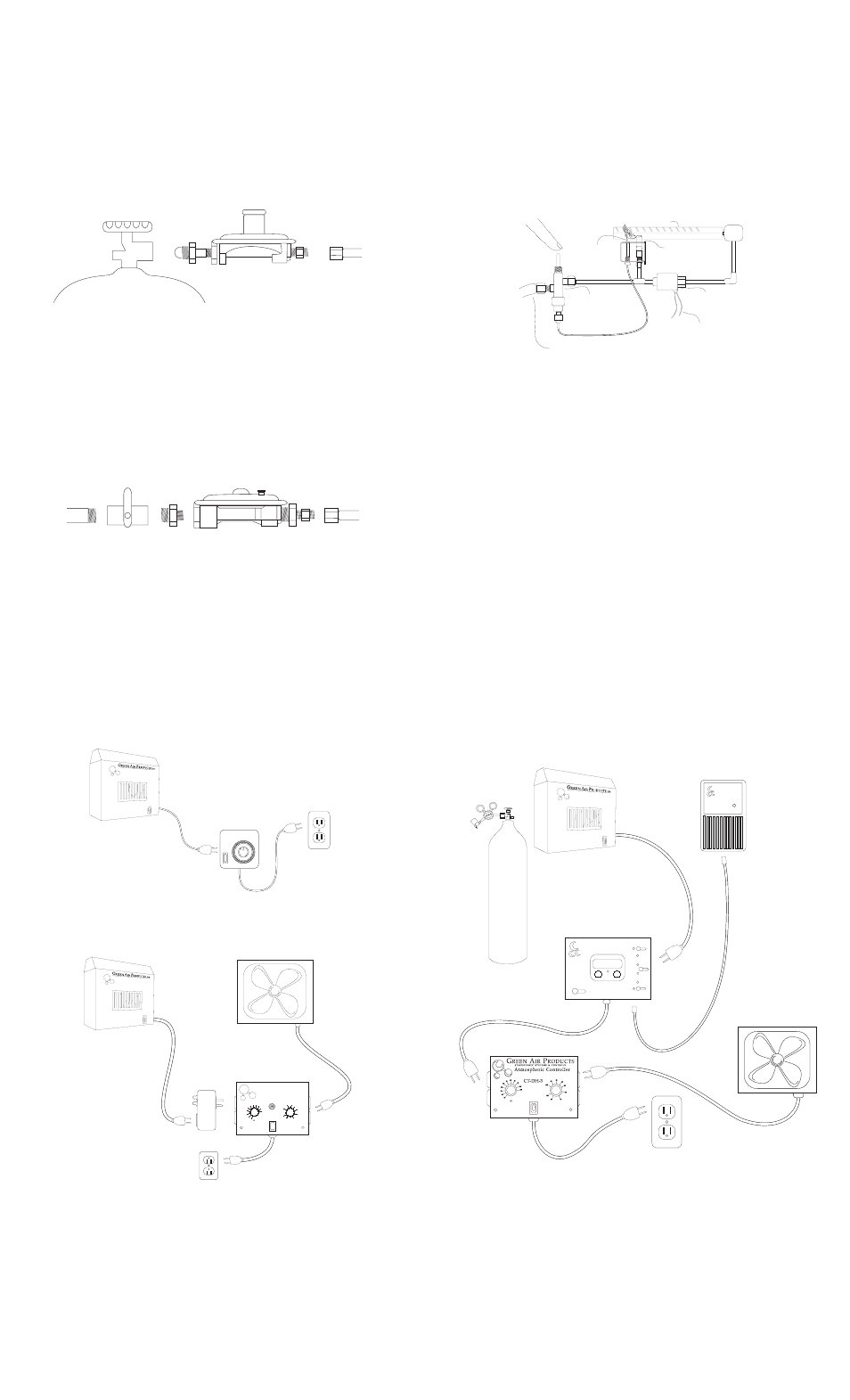
Generator Installation
1. Turn gas supply off before you begin work. Now connect a gas shut off
valve (not included) onto your incoming gas supply line. If needed reduce to
1/2 male nipple to accept enclosed regulator. Note gas flow direction indicator
arrow. Use gas compatible pipe compound on all pipe thread fittings and
tighten securely.
2. Connect regulator to shut off valve nipple with compound and tighten.
3. Check for gas leaks. A solution of 25% hand dish soap and 75% water in a
spray bottle will work well detecting gas leaks. Apply solution to all previously
connected fittings. Bubbles will occur around loose connections. Always use
two wrenches when tightening gas fittings.
Generator
hose
Regulator Assembly
Reducer
Nipple
Shut Off
Valve
Gas Supply
Line
Natural Gas Hook-up
Generator
hose
Regulator Assembly
Propane
Gas Tank
1. For propane applications use a propane tank that has been filled to only
80% of it’s capacity. This is very important for all propane burning mechanisms.
Failure to observe this common rule will make your generator hard to ignite
and will not stay lit (refer to troubleshooting).
2. Carefully thread the regulator flange nut in the tank valve counterclockwise
with your fingers until you feel the flange seat. Tighten firmly with adjustable
end wrench. DO NOT USE PLIERS! Fasten hose between regulator and
generator gas inlet in same fashion.
3. Turn the propane tank valve to wide open “ON” position.
4. Check for gas leaks. A solution of 25% hand dish soap and 75% water in
a spray bottle will work well for detecting gas leaks. Apply solution to all
previously connected fittings. Bubbles will occur around loose connections.
Always use two wrenches when tightening multiple fittings.
Propane Hook-up
WALL MOUNT
Bracket wall mount screw holes must be 10 inches center to center. Mount
brackets to wall and housing will slip over screw heads and fit snug into
slotted holes in housing back. This allows for easy removal of housing from
wall brackets. Make certain bracket screws are secure in wall and use good
judgement when choosing mounting location.
SUSPENDED
Use chain, eyebolts and ceiling hooks found in hardware pack. Hang unit
from sturdy location at least 18 inches from ceiling. The unit must operate in
level upright position. “CAUTION” Should unit fall during operation fire may result.
FREE STANDING
Remove the four screws holding the bottom plate to the housing. Locate the
holes on the bracket to match and replace the screws.
Igniting Pilot Burner
1. Plug the transformer into a grounded 110 volt timer or other power source.
2. Depress the RED button located on the inside of the generator for 90 seconds
to clear the air from the hose.
3. Once gas is present at the pilot let up button and wait 60 seconds for
excess gas to clear from the housing. Now depress the RED button again
and light the pilot burner. Maintain holding the button down for an additional
30 seconds to allow the thermocouple to heat to operating temperature.
4. Push the front on-off switch to the “ON position. Fuel will pass through the
solenoid valve and the main burner will be ignited by the pilot flame. As your
timer cycles on and off so will the main burner flame.
5. For the CD-18 and CD-36 , the brass needle valve may be used to very the
flame size. This will increase or decrease the time that the unit needs to
charge the area with CO2. The specs are based on the valve being fully open.
Junker Valve
Solenoid Valve
Burner
Pilot Light
Thermocouple
To solenoid valve
"On" "Off" switch
Gas feed hose from
regulator
Control Diagram
1
2
3
4
5
6
7
8
9
10
11
12
1
2
3
4
5
6
7
8
9
10
11
12
24 Hr.
Clock Timer
This example shows the simplest method of CO
2
generator control. Set the
Green Air ProductsTimestat, Cyclestat or PDT-1 timer for short intervals
during light hours only.
G
REEN
A
IR
P
RODUCTS
P R O F E S S I O N A L G R E E N H O U S E E Q U I P M E N T
CT-DH-3P
AtmosphericControlle
110
100
90
80
10
70
20
30
40
50
60
50
4
0
OFF
30
20
ON
60
70
80
This system is the ultimate in precise automated CO2 control. The CDM-6000
sensor continuously determines atmospheric CO2 values. The CDDS-2
controller interprets these values and provides flexible set point adjustments
to sequence CO2 equipment functions. The CDDS-1 has a built in photo
sensor to disable CO2 production during darkness. The CDMC-2 system can
be combined with the CT-DH-3 temperature and humidity controller to defeat
CO2 production during exhaust functions. The CO2 generator (or emitter
system) and the monitor are plugged into the CDDS-2 controller. CDDS-2
controller and the fan are plugged into the CT-DH-3 as shown. Plug the
power cord from the CDDS-2 controller into the left hand equipment outlet
on the CT-DH-3. The power to the sequencer will be interrupted when ever
the temperature or humidity conditions constitute an exhaust function. CO2
production will resume immediately after exhaust cycle is completed. Co2
levels will be maintained precisely and automatically. Order the CDMC-6 for
this Carbon Dioxide Monitor Controller combination.
Exhaust Syncronized Operation
This diagram demonstrates an exhaust synchronized system where the CO2
equipment is disabled during exhaust functions and immediately replenished
when exhaust is completed. The CT-DH-3P temperature and humidity
controller activates the exhaust fan and shuts off the CO2 during the exhaust
cycle. It has a built in photo sensor to limit CO2 enrichment to photoperiods
only. Enrichment will only occur when exhaust fan is off and light is present.The
CO2 “On” cycles are timed by the Cyclestat repeat cycle timer which cycles
the CO2 equipment according to your preset periods. An example might be
that the timer is set for 5 minutes every hour. The CO2 generator would be
operated according to that hour schedule. In the event that there is an exhaust
function at any time the CO2 will come on for 5 minutes immediately after the
exhaust cycle is completed. It will repeat again one hour after that point.
Replenishment of CO2 will always follow an exhaust cycle to maintain a
constant and continuous enrichment level.
PILOT LIGHT FAILS TO IGNITE:
Make sure propane tank has fuel and valve is fully open. For natural gas
generators make sure gas supply is "On" and shut off valve is open. Make
sure propane tank has not been overfilled. If so, take tank outdoors and open
valve to release gas for a few seconds and reconnect. Remember red button
must be depressed to light pilot.
PILOT LIGHT WON’T STAY LIT:
Hold the red button down to clear all pockets of air from inside the hose. Make
sure the propane tank has not been overfilled. If so, take tank outdoors and
open valve to release gas for a few seconds and reconnect. Remember, red
button must be depressed for 30 seconds or until the thermocouple heats to
operating temperature and holds pilot open.
BURNER FAILS TO IGNITE:
Check that the tank valve is fully open. Be sure all air has bled from the hose
and gas is present. Make sure the transformer is plugged into a working power
source. Make sure power indicator switch is in “ON” position. Check that
needle valve is open.
BURNER WON’T STAY LIT:
Check that needle valve is open enough to support a strong minimum flame.
Check timer and power source operation.
FLAME BURNS IRREGULAR:
Dirt or residue could constrict burner orifice. Low fuel pressure due to depleted
or contaminated fuel supply. Lack of oxygen content in room due to inadequate
fresh air intake. Excessive air movement or gust from fan or ventilation.
Generator not setting level.
Trouble Shooting Tips (see www.greenair.com for further information)