Global Specialties 1310 User Manual
Page 11
3.7
OPERATION :
Proper operation of most circuitry depends on correct voltage. It is
recommended that the variable supplies be set to the required
voltage levels with their loads disconnected. When the desired
voltage is set ( using the A or B voltage control ), turn the AC power
off, connect each load to the proper supply, and turn the AC power
on.
Output voltage may be continuously monitored by setting the V / A
meter switch to the V position, setting the A / B switch to the desired
supply position, and reading the output voltage on the digital
display, Output current may be read by simply changing the V / A
switch from the V to the A position.
3.8
GROUNDING
All three power supplies are isolated and may be operated without
any reference to earth ground. If an earth reference is required, one
terminal ( either + or - ) from any one, two, or all three supplies may
be connected to the earth ground binding post.
3.9
CURRENT LIMITING :
Each power supply is protected against output short circuit. If any
output is short-circuited, the voltage drops to zero and the current
is limited to a safe value.
3.10
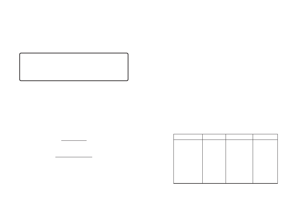
COMBINING POWER SUPPLY :
Each of the three supplies may be used independently, or in a
combination of any two or all three. These combinations, outlined
in figure 2 and described below, can yield increased voltage
ranges, increased current capability, or a split plus and minus
supply such as frequently used in analog circuitry.
Power Supply Connection Voltage Range Max. Current
5V
--
5 Volts
1.0 Amps
A ( variable )
--
1.3 to 20Volts 250 Milliamps
B ( variable )
--
1.3 to 20Volts 250 Milliamps
A + B
Parallel 1.3 to 20Volts 500 Milliamps
A + B
Series 2.6 to 40Volts 250 Milliamps
5V + A or B
Series 6.3 to 25Volts 250 Milliamps
5V + A + B
Series 7.6 to 20Volts 250 Milliamps
A + B
Split Supply +1.3 to +20Volts, 250 Milliamps
-1.3 to -20V
Figure 2 : Power Supply Interconnections
7
Specifications subject to change without notice.
!!Copyright 1994, INTERPLEX ELECTRONICS, INC,
Unit No.2, Highland Industrial Centre 1486, Highland Avenue,
Cheshire CT 06410, U.S.A.
!!and TM trademarks are the property of INTERPLEX
ELECTRONICS, INC, Unit No.2, Highland Industrial Centre 1486,
Highland Avenue, Cheshire CT 06410, U.S.A.
CASE DISASSEMBLY AND ASSEMBLY
WARNING
Potentially lethal AC power is present whenever the line cord is plugged
into the AC outlet, even when the power switch is OFF. Always
disconnect the power cord when opening the case. Avoid touching the
fuse post on the inside of the unit.
Should access to the inside of the unit be required, proceed a follows:
1.
Remove the line cord from the AC outlet before disassembly.
2.
To disassemble the case, remove the screws that secure the cover to
the chassis and lift the cover off.
3.
To reassemble the case, place the cover on the chassis, line up the
screw holes, and replace the screws.
MAINTENANCE AND RECALIBRATION
ADJUSTMENTS
All circutry is factory-calibrated. No user adjustments are required.
FUSE REPLACEMENT
Remove the line cord from the AC outlet before changing fuses. Using a
screwdriver, remove the fuse holder cap. Replace the fuse with another fuse
of identical type and current rating. Replace the fuse holder cap.
14