Global Specialties 1523 - Manual User Manual
Page 8
SECTION - 5
REMOTE COMMUNICATION
5.1
INTRODUCTION
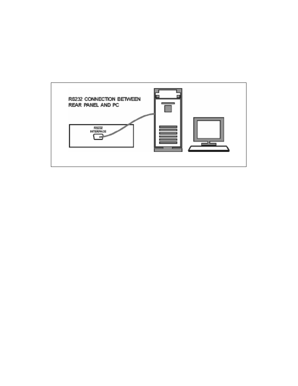
By using the remote communication facility and the set of remote commands, a PC can
completely control the instrument and get information from it. During remote communication,
front panel is disabled (except Go Local key) as long as the remote PC doesn’t relinquish control
of the instrument or the GO Local key on front panel is pressed. Follow the diagram below for
connections.
Fig. 4 Serial communication Connections
a) Connect the com port of the PC to the female 9 pin D-type ‘RS232’ interface connector (5)
on the rear panel of the instrument.
b) Run any communication software like hyper terminal on the PC to communicate to the
instrument.Communication protocols are described as under.
5.2
COMMANDS FOR COMMUNICATION
Note : 1.Set Baud Rate = 9600 bits per second for serial communication.
Command Set:-
1. RV - Set ‘V’ function & Read input voltage in volts.
e.g. XXX.X ‘V’
2. RI - Set ‘I’ function & Read load current in amperes.
e.g. X.XXX ‘A’ or XX.XX ‘A’
3. RP - Set ‘P’ function & Read apparent power in Volt-Amperes.
e.g. XXXX ‘VA’
4. RW - Set ‘W’ function & Read Actual power in Watts.
e.g. XXXX ‘W’
5. RF - Set ‘F’ function & Read mains frequency in Hz.
e.g. XX.XX ‘Hz’
6. GL - To come out of Remote operation (i.e. Local Mode). This command is acknowledged by
an answerback character. i.e. ’Y’.
7. SA - To enter into auto scan mode of all parameters. This command is acknowledged by an
answerback character. i.e. ’Y’.
8. Z - To flush buffer.
Note : To come out of Remote mode, GL switch on front panel can also be used.