GeoVision ST124SLD User Manual
Page 3
May 13, 2011
5
Connecting to the GV-AS Controller
To connect the electric strike to the GV-AS Controller, follow the steps below. Here we use
the GV-AS400 Controller for example.
1. To connect the power between the electric strike and the GV-AS400, refer to the diagram
as below.
Figure 5
Connect one black wire of the electric strike to COM on GV-AS400, connect the other
black wire of the electric strike to the (-) point on the external power supply, and connect
the (+) point on the external power supply to NO on GV-AS400.
2. To connect the sensor to the GV-AS400, connect the Yellow wire of the sensor to the
Input of the GV-AS400, and connect the White wire of the sensor to the Ground of the
GV-AS400.
Figure 6
May 13, 2011
6
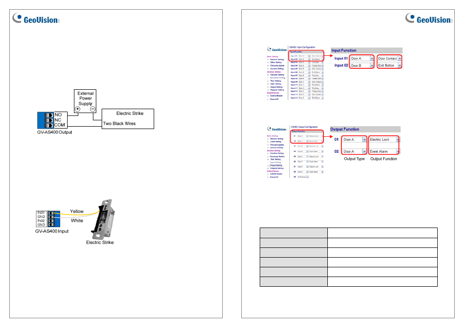
3. On the Web interface of the GV-AS400, select Input Setting, and select an input type
and input function for the connected sensor from the electric strike.
Input Type
Input Function
Figure 7
4. On the Web interface of the GV-AS400, select Output Setting, and select an output type
and output function for the connected electric strike.
Figure 8
For details on configuring the input and out devices, see 3.4.3.D Input Function and 3.4.3.E
Output Function on the GV-AS Controller User’s Manual.
Specifications
Voltage
DC 12V (default) or DC 24V
Current Draw
260mA at DC 12V or 150mA at DC 24V
Keeper Depth
12.7 mm / 0.50 in
Temperature Resistance
-30°C ~ 80°C / 20 °F ~ 160 °F
Dimension (L x W x H)
123.5 x 31.4 x 40.7 mm / 4.86 x 1.24 x 1.60 in
Certification
CE