GeoVision ST124SLD User Manual
Page 2
May 13, 2011
3
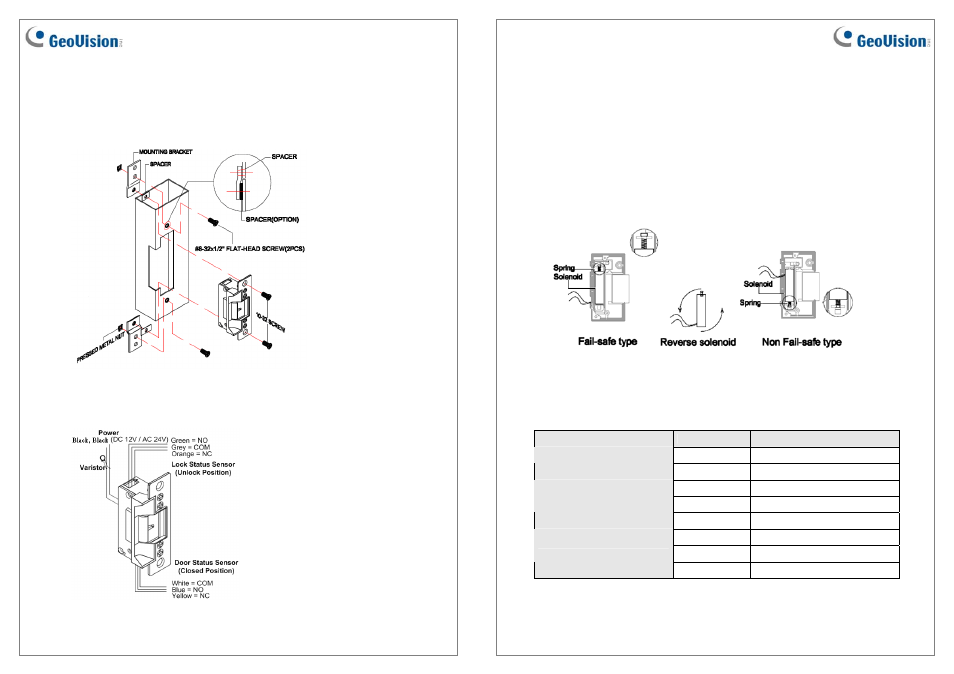
3. Spacers are provided to ensure the final assembly of faceplate into the doorjamb. Add
one of spacers between the doorjamb and the mounting bracket when faceplate extends
beyond the doorjamb. When the faceplate sets inside the jamb, spacers must be added
between the mounting bracket and the tip bracket. Make sure the clearance hole in the
spacer aligns with the hole in the mounting bracket.
Figure 2
4. Connect the wires from the low voltage side of the transformer to the black wires of the
electric strike.
Figure 3
May 13, 2011
4
5. Install the electric strike to the doorjamb by using the #10-32 screws and the lock
washers (Figure 2).
6. Tighten the #8-32 flat-head screws to hold the mounting brackets to the doorjamb (Figure
2).
7. To prevent strike from spike, connect the Varistor between the input power wires (Figure
3).
8. To modify fail-safe to non fail-safe or vice versa.
A. Unscrew the electric strike as illustrated below.
B. Reverse the solenoid to the opposite side and then close.
Figure 4
Wire Definition
Wire
Definition
Black
Positive (+) or Ground (-)
Electric Bolt
Black
Positive (+) or Ground (-)
Green NO
Grey COM
Lock Status Sensor
Orange NC
Blue NO
White COM
Door Status Sensor
Yellow NC