GeoVision ML200SLD User Manual
Page 2
May 13, 2011
3
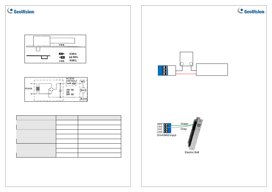
Auto-lock Time Delay Setting
Use Jumper inserted on the electric bolt to set a lock-delayed time, after which the door will
automatically be locked. There are 3 options: 0, 2.5 and 5 seconds.
Wiring Instruction
Wire Definition
Wire
Definition
Red Positive
(+)
Electric Bolt
Black Ground
(-)
Blue NO
White COM
Lock Status Sensor
Yellow NC
Green NO
Grey COM
Door Status Sensor
Orange NC
May 13, 2011
4
Connecting to the GV-AS Controller
To connect the electric bolt to the GV-AS Controller, follow the steps below. Here we use the
GV-AS400 Controller for example.
1. To connect the power between the electric bolt and the GV-AS400, refer to the diagram
as below.
External
Power
Supply
Electric Bolt
+
_
NC
COM
GV-AS400 Output
NO
Black Wire
Red Wire
Connect the Red wire of the electric bolt to COM on GV-AS400, connect the Black wire
of the electric bolt to the (-) point on the external power supply, and connect the (+) point
on the external power supply to NC on GV-AS400.
2. To connect the sensor to the GV-AS400, connect the Green wire of the sensor to the
Input of the GV-AS400, and connect the Grey wire of the sensor to the Ground of the
GV-AS400.