GeoVision MLSH01-0 User Manual
Page 2
May 13, 2011
3
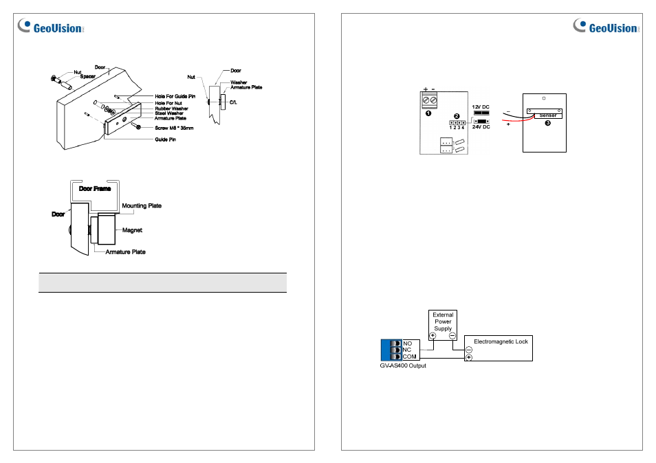
2. Mounts the armature plate to the door.
Typical Installation of the electromagnetic lock:
Note: To make the armature plate adjust its proper position to the magnet automatically,
do not fix the armature plate too tightly and make the rubber washer more flexible.
May 13, 2011
4
Contacts
Unscrew the cover of electromagnetic lock and you will see the diagram as below:
1. Power Terminal Block: Connects to the DC 12V / 24V power source.
2. Power Switch Jumper: Plug the power jumpers to Pins 1, 2 and Pins 3, 4 for a 12V
DC power source. Plug the power jumper to Pins 2, 3 for a 24V DC power source.
3. Sensor: Connects to the access control system by using the black and red wires. For
details, see Connecting Sensor to the Access Control System later in this installation
guide.
Connecting to the GV-AS Controller
To connect the electromagnetic lock to the GV-AS Controller, follow the steps below. Here
we use the GV-AS400 Controller for example.
1. To connect the power between the electromagnetic lock and the GV-AS400, refer to the
diagram as below.
Connect the (+) point on the electromagnetic lock to COM on GV-AS400, connect the
two (-) points of the electromagnetic lock and the external power supply together, and
connect the (+) point on the external power supply to NC on GV-AS400.