Brooks – Brooks Instrument 1255 User Manual
Page 2
Brooks
®
1250-55 Series Flowmeters
Installation and Operation Manual
X-VA-1250-55 Series-eng
Part Number: 541B164AAG
May, 2011
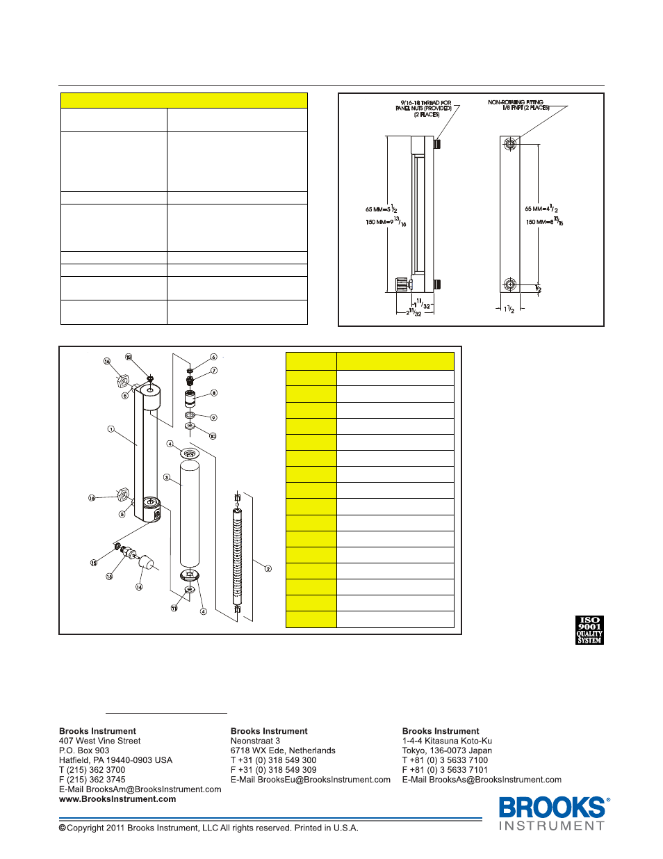
Figure 1 Dimensions for Brooks 1250-55 Series Flowmeters
Due to Brooks Instrument’s continuous improvement of our products, all specifications are subject to change without
notice. When ordering parts please include part description, item number (see Figure 2) and type of material required.
If you have any questions regarding installation, maintenance, replacement or use of this flowmeter, please visit our
website at www.BrooksInstrument.com for Customer Service contact information.
Figure 2 Parts List for Brooks 1250-55 Series Flowmeters
Number
Description
1
Frame Assembly
2
Tube Assembly
3
Lens
4
Lens End Cap(s)
5
Fitting
6
Jack Screw O-ring
7
Jack Screw
8
Jack Plug
9
Jack Plug O-ring
10
Top Gasket
11
Bottom Gasket
12
Retaining Clip
13
Optional Valve
14
Valve Knob
15
Valve O-ring
16
Panel Nuts
SPECIFICATIONS
ACCURACY:
± 10% Full Scale – 65 mm
± 5% Full Scale – 150 mm
FLOATS:
Black Glass Ball Float
Sapphire Ball Float
Stainless Steel Ball Float
Tungsten Carbide Float
Tantalum Float
FRAME BACKPLATE:
Anodized Aluminum
END BLOCKS AND
ELASTOMERS:
Aluminum with Buna-N
Brass with Buna-N
Stainless Steel with Viton®
fluoroelastomer
FITTINGS:
⅛-27 FNPT Fittings
GLASS TUBE:
Precision Formed Borosilicate
MAXIMUM
TEMPERATURE:
200°F (93 °C)
MAXIMUM
PRESSURE:
200 PSI (13.8 Bar)