Biamp ELD-1 User Manual
Page 6
Speaker Line Connector
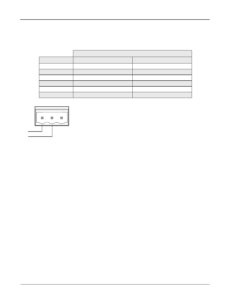
A plug-in barrier-strip connector on the ELD-1 connects the device to the end of the speaker line. The device needs to be connected to an
appropriate monitoring point on the speaker cable—typically after the last speaker on the run. Connect the speaker line between the Com
pin and the appropriate Low or High pin as defined in the table below.
Output Fault Detection
The Amplifier monitors (supervises) for faults on speaker connections using a combination of multiple out-of-band (inaudible) high frequency
tones.
For end-of-line detection, one or more (up to 15 maximum) ELD-1 units can be connected to the speaker line. To ensure correct operation of fault
detection it is necessary to follow these guidelines:
• Recorded audio messages or audio content with continuous or swept tonal components (e.g. alert tones) and any content with
significant high frequency harmonic content should be band limited (>24dB/octave) at 15 kHz during recording. Note that program
content that is distorted due to poor recording techniques may contain excessive high frequency harmonics.
• Signal level adjustments within a Vocia system should be set so as to minimize clipping. Severely clipped signals may also affect
the out-of-band fault detection tones.
• The use of speaker cables that inherently attenuate high frequencies is not supported (e.g. screened cables). Speaker cables must
maintain frequency response to the end of line of less than -3dB @ 20kHz at with respect to 1kHz.
• Speaker cables longer than 500 feet may prevent correct operation of ELD and Ground Fault monitoring capabilities. An advantage
of Vocia is that amplifiers may be easily distributed close to speakers, thereby minimizing long runs of expensive and potentially
lossy speaker cable.
• Highly capacitive speaker lines or loads may prevent correct operation of the ELD detection system.
• Legacy monitored speaker circuits that use capacitors and resistors or similar methods must have all legacy monitoring circuitry
removed for correct operation of the ELD detection system.
• For EN 54-16 compliance, one or more ELD units must be fitted. End of Line detection must be enabled in the Vocia software.
Fault Indication
When a fault is detected on the speaker line or amplifier channel, the lower left LED on the RJ-45 socket will illuminate Amber and remain
on until the fault is resolved. Providing a valid PoE power source and Ethernet connectivity is available the ELD-1 the solid amber indicator
can be used to physically identify the ELD-1 that is reporting an issue.
6
ELD-1 SETUP AND USE
End of Speaker Line
High
Low
Com
Amplifier Power
Speaker Circuit
Less than 100 Watts
100 Watts or greater
4Ω
Low
Low
6Ω
Low
Low
8Ω
Low
Low
25 Volt
Low
Low
70 Volt
Low
Low
100 Volt
Low
High
Note that for circuits connected to the Low terminal the ELD-1 presents a 0.5 Watt load to a 70V circuit and a 1 Watt load to a 100V circuit.