Installation wiring, Panel din rail mounting, Wiring to input terminals – Flowline LC52 DataPoint User Manual
Page 4: Setting input polarity, Repeater output, Step four step five, Sourcing mode, Sinking mode, Display, 36 vdc power
Step Four
Step Five
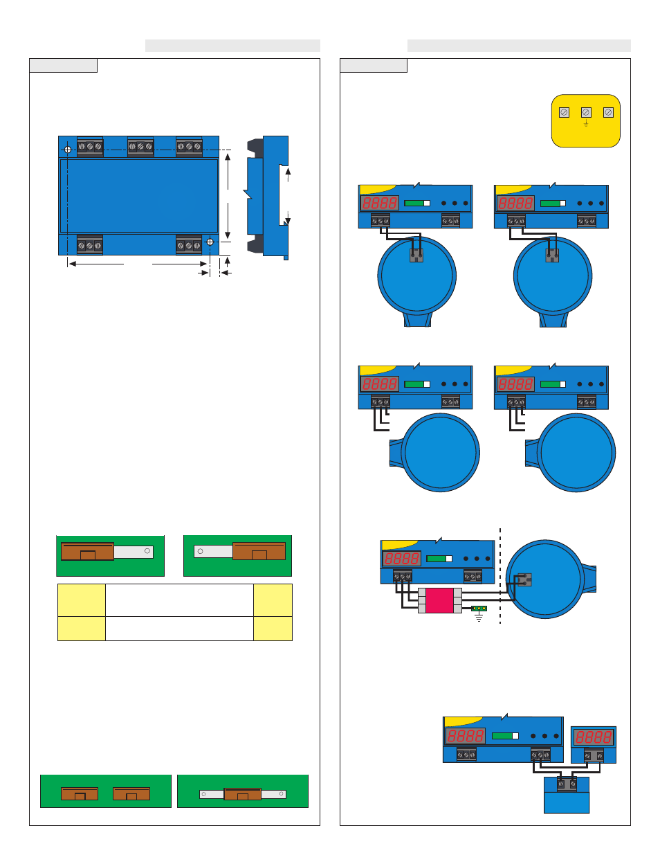
INSTALLATION
WIRING
Panel DIN Rail Mounting
The controller may be mounted by either a back panel using two
screws through mounting holes located at the corners of the controller
or by snapping the controller on 35 mm DIN Rail.
Wiring to Input Terminals
Signal input is always through the 24 VDC terminal.
The 28 VDC terminal is used as an alternative
power supply for three-wire devices. Please note a
difference between 2-wire and 3-wire level trans-
mitters and sourcing and sinking modes below.
Two-wire Transmitter
Two-wire Transmitter
(Sourcing Mode / JWA)
(Sinking Mode / JWB)
Three-wire Transmitter
Three-wire Transmitter
(Sourcing Mode / JWA)
(Sinking Mode / JWB)
Intrinsically Safe Two-wire Transmitter LU20-5001-IS
(Sinking Mode / JWB)
Note: Always install the controller in a location where it does not
come into contact with liquid.
Setting Input Polarity:
The LC52 can be set in one of two modes, sourcing and sinking. The
LC52 is shipped from the factory in the sourcing mode. This is compat-
ible with the LA12-_0_1, LA15-50_1, LP75-20_1, LU20-50_1, LU30-
50_4 and LU35-50_4 with no adjustment required. If using a LU30-
50_3, LU35-50_3 and LU20-50_1-IS, follow the instructions below.
1. Remove the back panel of the controller and gently slide the
printed circuit board (PCB) from the housing. Use caution when
removing the PCB.
2. Locate jumpers JWA and JWB on the PCB.
3. To change from sourcing to sinking, remove jumper from JWA
and place on JWB. The LC52 is shipped from the factory in the
sourcing mode (JWA active).
4. Gently return PCB into housing and replace back panel.
Note: Loop powered devices can operate in either the souring or sink-
ing modes. Please see step 4 for proper wiring instructions.
Changing from 120 to 240 VAC:
1. Remove the back panel of the controller and gently slide the printed
circuit board from the housing. Use caution when removing the
PCB.
2. Located jumpers JW1, JW2 and JW3 on the PCB.
3. To change to 240 VAC, remove jumpers from JW1 and JW2 and
place a single jumper across JW3. To change to 120 VAC, remove
jumper JW3 and place jumpers across JW1 and JW2.
4. Gently return PCB into housing and replace back panel.
120 VAC
240 VAC
Repeater Output:
The isolated repeater
output reproduces the
input current signal.
External power is
required and should
not exceed a maxi-
mum of 36 VDC.
LB10-1001
LU20-5001-IS
Stahl Barrier
Intrinsically Safe
9001/51-280-110-14
Level Transmitter
Voc = 28.0 V
Vmax = 32 V
Isc = 105.9 mA
Imax = 130 mA
Ca = 0.14 µF
Ca = 0 µH
La = 3.2 mH
La = 0 mF
3.475"
2.2"
.275"
.225"
Continuous
Controller
EASY CAL
UP
DOWN
SET
4
20
OP
INPUT
0%
100%
O
F
F
S
E
T
S
P
A
N
R
LY
1
R
LY
2A
R
LY
2B
Display
+ -
12-36 VDC
POWER
+ -
Sourcing Mode
JWA
JWB
Sinking Mode
JWA
JWB
120 VAC
JW2
JW3
JW1
240 VAC
JW2
JW3
JW1
LU30-50_4, LU50-70_4, LU20-50_1,
LU05-5__1, LU1_-5__1, LU8_-51_1,
LV5_-S001 & LD1_-S001
LU30-50_3, LU50-70_3 & LU20-50_1-IS
No Change
Required
Change
Required
Sourcing
Device
Sinking
or Loop
Devices
35 mm
DIN Rai
l
4
(+) (-)
Two-Wire
Loop Powered
Level
Transmitter
Continuous
Controller
EASY CAL
UP
DOWN
SET
4
20
OP
INPUT
0%
100%
O
F
F
S
E
T
S
P
A
N
R
LY
1
R
LY
2A
R
LY
2B
4
(+) (-)
Two-Wire
Loop Powered
Level
Transmitter
Continuous
Controller
EASY CAL
UP
DOWN
SET
4
20
OP
INPUT
0%
100%
O
F
F
S
E
T
S
P
A
N
R
LY
1
R
LY
2A
R
LY
2B
Continuous
Controller
EASY CAL
UP
DOWN
SET
4
20
OP
INPUT
0%
100%
O
F
F
S
E
T
S
P
A
N
R
LY
1
R
LY
2A
R
LY
2B
4
Three-Wire
Sourcing
Level
Transmitter
Models:
LU30-50_3
LU50-70_3
White
Black
Red
Continuous
Controller
EASY CAL
UP
DOWN
SET
4
20
OP
INPUT
0%
100%
O
F
F
S
E
T
S
P
A
N
R
LY
1
R
LY
2A
R
LY
2B
4
(+) (-)
Two-Wire
Loop Powered
Level
Transmitter
Zener
Barrier
Non-Hazardous Area Hazardous Area
3
4
G
1
2
G
Continuous
Controller
EASY CAL
UP
DOWN
SET
4
20
OP
INPUT
0%
100%
O
F
F
S
E
T
S
P
A
N
R
LY
1
R
LY
2A
R
LY
2B
4
Three-Wire
Sourcing
Level
Transmitter
Models:
LU30-50_4
LU50-70_4
White
Black
Red
INPUT
( + )
28 VDC
50 mA
Max.
GND
( + )
( )
24 VDC
25 mA
Max.