Safety precautions guide to controls – Flowline LC52 DataPoint User Manual
Page 3
Step Two
Step Three
SAFETY PRECAUTIONS
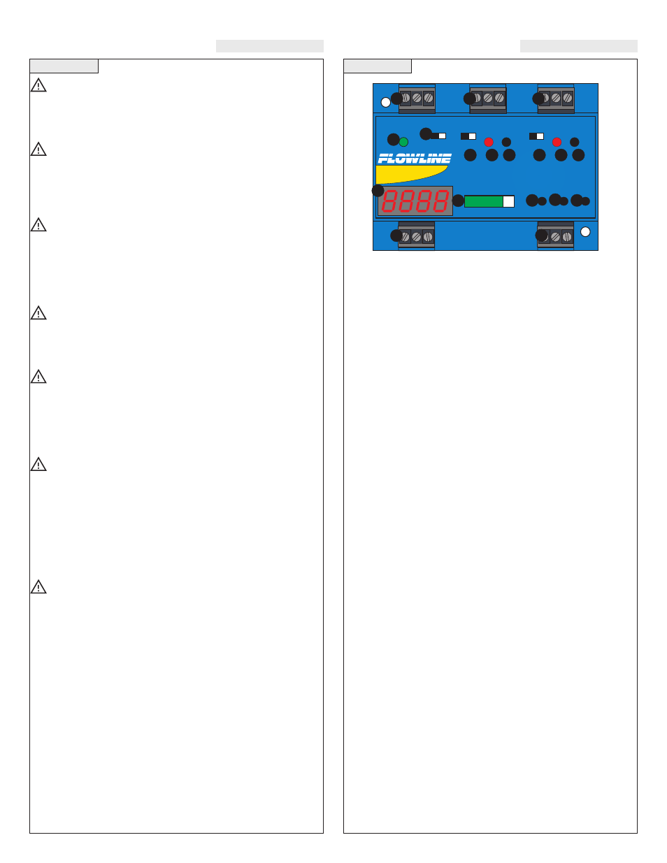
GUIDE TO CONTROLS
About This Manual:
PLEASE READ THE ENTIRE MANUAL PRIOR TO
INSTALLING OR USING THIS PRODUCT. This manual includes
information on the Continuous Relay Controllers from Flowline:
LC52-1001.
User’s Responsibility for Safety:
Flowline manufactures several models of controller, with different
mounting and switching configurations. It is the user’s responsibil-
ity to select a controller model that is appropriate for the applica-
tion, install it properly, perform tests of the installed system, and
maintain all components.
Electrical Shock Hazard:
It is possible to contact components on the controller that carry high
voltage, causing serious injury or death. All power to the controller
and the relay circuit(s) it controls should be turned OFF prior to work-
ing on the controller. If it is necessary to make adjustments during
powered operation, use extreme caution and use only insulated tools.
Making adjustments to powered controllers is not recommended.
Flammable or Explosive Applications:
LC52 series remote mount controllers should not be used with explo-
sive or flammable liquids, which require an intrinsically safe rating.
If you are unsure of the suitability of a controller for your installation,
consult your Flowline representative for further information.
Install In a Dry Location:
The controller housing is not designed to be immersed. It should
me mounted in such a way that it does not come into contact with
liquid. Its case is made out of PP (polypropylene). Refer to an
industry reference to ensure that compounds that may splash onto
the controller housing will not damage it. Such damage is not cov-
ered by the warranty.
Relay Contact Rating:
The relay is rated for a 10 amp resistive load. Many loads (such as
a motor during start-up or incandescent lights) are reactive and
have an inrush current characteristic that may be 10 to 20 times
their steady-state load rating. The use of a contact protection circuit
may be necessary for your installation if the 10 amp rating does not
provide an ample margin for such inrush currents. In critical appli-
cations, redundant backup systems and alarms must be used in
addition to the primary system. Such backup systems should use
different sensor technologies where possible.
Make a Fail-Safe System:
Design a fail-safe system that accommodates the possibility of
relay or power failure. If power is cut off to the controller, it will
de-energize the relay. Make sure that the de-energized state of the
relay is the safe state in your process. For example, if controller
power is lost, a pump filling a tank will turn off if it is connected to
the Normally Open side of the relay.
While the internal relay is reliable, over the course of time relay
failure is possible in two modes: under a heavy load the contacts
may be “welded” or stuck into the energized position, or corrosion
may build up on a contact so that it will not complete the circuit
when it should. In critical applications, redundant backup systems
and alarms must be used in addition to the primary system. Such
backup systems should use different sensor technologies where pos-
sible.
While this manual offers some examples and suggestions to help
explain the operation of Flowline products, such examples are for
information only and are not intended as a complete guide to
installing any specific system.
1. Power indicator: This Green LED lights when AC power is
ON.
2. Relay indicator: This Red LED will light whenever the control-
ler energizes the relay, in response to the transmitter input and
after the time delay.
3. AC Power terminals: Connection of 120 VAC power to the
controller. The setting may be changed to 240 VAC if desired.
This requires changing internal jumpers; this is covered in the
Installation section of the manual. Polarity (neutral and hot) does
not matter.
4. Relay terminals (NC, C, NO): Connect the device you wish to
control (pump, alarm etc.) to these terminals: supply to the COM
terminal, and the device to the NO or NC terminal as required.
The switched device should be a non-inductive load of not more
than 10 amps; for reactive loads the current must be derated or
protection circuits used. When the red LED is ON and the relay is
in the energized state, the NO terminal will be closed and the NC
terminal will be open.
5. Invert switch: This switch reverses the logic of the relay control
in response to the switch(es): conditions that used to energize the
relay will now de-energize the relay and vice versa.
6. Time delay: Sets delay from 0 to 60 seconds. Hold Delay button
to increase delay in 5 second increments.
7. Digital display: Shows the current 4-20 mA signal in engineer-
ing units.
8. Input terminals: Connect the transmitter wires to these termi-
nals: A 24 VDC power is provided for current loop with an addi-
tional 28 VDC power terminal if required.
9. Latch switch (relay 2): This switch determines how the relay
will be energized in response to the two set points. When LATCH
is OFF, the relay responds to set point RLY2A only; when LATCH
is ON, the relay will energize or de-energize only when both set
points (RLY2A and RLY2B) are in the same condition (both wet
or both dry). The relay will remain latched until both set points
change conditions.
10. Bar Graph: Displays 4-20 mA signal as a percentage of the
range.
11. OP / SET: Used to scroll between set points during program-
ming.
12. 20 / Down: Used to decrease display value during programming
and for EasyCal™ Span set up.
13. 4 / Up: Used to increase display value during programming and
for EasyCal™ Offset set up.
14. Repeater Output: Isolated terminal which reproduces the input
4-20 mA signal. Terminal requires 12-36 VDC power for opera-
tion.
4
Continuous
Controller
RELAY 1
RELAY 2
P O W E R
EASY CAL
INVERT
DELAY
INVERT
DELAY
UP
DOWN
SET
4
20
OP
INPUT
0%
100%
O
FF
S
ET
SP
AN
R
LY
1
R
LY
2A
R
LY
2B
ON OFF
LATCH
3
4
4
1
9
5
6
2
5
6
2
7
8
14
10
13
12 11