Troubleshooting, Examples – Flowline LC8X Thermo-Flo User Manual
Page 6
Step Eight
Step Nine
TROUBLESHOOTING
Controller Logic:
For all controllers, please use the following guide
to understand the operation of the Flowline LC80/LC82 controllers.
1. Make sure the Green power LED is On when power is supplied to
the controller.
2. For NC switch wiring, the input LED's on the controllers will be
Amber when the switch reads no-flow and Off when the switch
reads flow.
3. The input LED will always respond to its corresponding relay
LED. With invert Off (-), the relay LED will be On when the input
LED is On and Off when the input LED is Off. With invert On (+),
the relay LED will be Off when the input LED is On and On when
the input LED is Off.
4. The relay may be wired either NO or NC. The normal state of the
relay is when its LED is Off. With the LED On, the relay is in the
energized mode and all terminal connections are reversed.
5. LC82 model only, Latch ON operation: When both input LED's
are ON, the relay will be energized (red LED On). After that, if
one switch input turns Off, the relay will remain energized. Only
when both switch LED's are Off will the controller de-energize
the relay. The relay will not energize again until both switch
LED's are ON. Reversing Invert switch will reverse logic. See the
Logic Chart below for further explanation.
Set Points:
If the preset factory calibration is not adequate for
your application, follow the calibration steps listed below. Note: the
switch's internal LED will be on when the switch detects no-flow and
will off when the switch detects flow.
1. Install the fitting and flow switch as described in the Installation
section of this manual. Turn the flow switch and controller power
on and adjust the flow rate to the application setting. If the medi-
um to be sensed is likely to be subject to high temperature varia-
tions, the flow switch should be set at the highest normal temper-
ature likely to be encountered.
2. Locate the potentiometer knob at the top of the flow switch. The
red LED is visible through the potentiometer. (If the LED is on,
slowly adjust the potentiometer counterclockwise, with a small
flat head screwdriver until the LED turns off.) The adjustment is
a single turn 270° potentiometer. The initial response time of the
flow switch after adjustment is 1 to 10 seconds. Adjust the poten-
tiometer in slow increments and wait for the response.
If the LED is off, slowly adjust the potentiometer clockwise until
the light turns on. Then turn the potentiometer counterclockwise
to bring the LED off at a reliable setting. Remember, adjust the
potentiometer in slow increments and wait for the response.
3. Verify that the new calibration is correct by lowering the system
flow rate below the set point and check to see that the red LED
turns on. Then increase the flow rate above the set point and ver-
ify that the red LED turns off accordingly.
Liquid Switch
Gas Switch
FT10-___5 Series
GT10-___5 Series
EXAMPLES
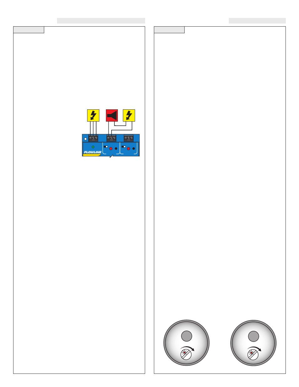
Low Flow Alarm:
The goal is to indicate when the flow rate falls
below a certain point. If it does, an alarm is supposed to sound, alert-
ing the operator of a low flow condition.
If power is accidentally cut to the controller, the sensor's ability to
notify the operator of a low flow condition could be lost. The system
must alert the operator not only to low flow, but to controller power
loss. To do this, connect the hot lead of the alarm to the NC side of
the relay terminal of the controller. If power is lost, the relay will be
de-energized, and the alarm will sound (if there is still power to the
alarm circuit itself). The alarm circuit should have a non-interruptible
power supply or some other indicator or backup alarm to warn of a
power failure in the alarm circuit.
In this application, the normal status
is when the sensor is in the flow con-
dition, and the relay will be energized
holding the alarm circuit open. If the
switch is wired NC, the input LED
will be off and the relay LED will
be on. So for this application,
Invert should be set to the On posi-
tion. If the switch is wired NO, the
input LED and the relay LED will
be on simultaneously . So for this appli-
cation, Invert should be set to the Off (-) position.
R E L A Y 1
R E L A Y 2
P O W E R
- +
- +
I N V E R T
D E L A Y
I N V E R T
D E L A Y
Invert ON (+) setting
1 fps
90 fps
10 fps
.04 fps
3 fps
0.2 fps