Installation, Vac power input wiring, Relay input wiring – Flowline LC8X Thermo-Flo User Manual
Page 5: Led indication, Connecting relay switches to input terminals, Step six step seven, 240 vac, Ft10 gt10
Step Six
Step Seven
INSTALLATION
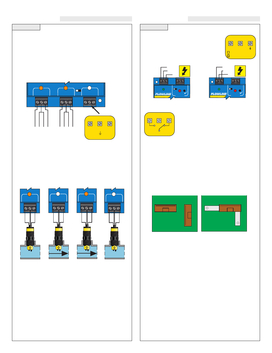
VAC Power Input Wiring
Observe the POWER SUPPLY label on the LC80
series. The label identifies the power requirement
(120 or 240 VAC) and the terminal wiring. Note:
Polarity does not matter with the AC input termi-
nal.
Relay Input Wiring
The relay is a single pole, double throw type rated
at 250 Volts AC, 10 Amps. The two terminal NO
and NC (normally open and normally closed) will
be used in different applications. Remember that
the "normal" state is when the relay coil is de-
energized and the Red relay LED is Off / de-ener-
gized.
Changing from 120 to 240 VAC
1. Remove the back panel of the controller and gently slide the printed
circuit board from the housing. Use caution when removing the PCB.
2. Located jumpers JW1, JW2 and JW3 on the PCB.
3. To change to 240 VAC, remove jumpers from JW1 and JW2 and
place a single jumper across JW3. To change to 120 VAC, remove
jumper JW3 and place jumpers across JW1 and JW2.
4. Gently return PCB into housing and replace back panel.
120 VAC
JWB
JWA
J
W
C
240 VAC
JWB
JWA
J
W
C
R E L A Y 1
P O W E R
- +
I N V E R T
D E L A Y
Ground
Neutral
Hot
R E L A Y 1
P O W E R
- +
I N V E R T
D E L A Y
Ground
Neutral
Hot
POWER
120 VAC, 50 - 60 Hz
L1
240 VAC, 50 - 60 Hz
L2
( )
NO
NC
RELAY OUTPUT
250 VAC, 10 A
C
INSTALLATION
LED Indication:
Use LED's located above the input terminals to indicate whether the
switch is in a Flow or No-Flow state. With the flow switch wired NC,
the Amber LED indicates No-Flow and no LED indicates flow.
Wiring the switch NO (reversing the Red and Black wires), the Amber
LED indicates Flow and no LED indicates No-Flow.
NC Wiring
NC Wiring
NO Wiring
NO Wiring
Amber
OFF
Amber
OFF
I N P U T 1
B
la
c
k
R
e
d
W
h
it
e
G
re
e
n
I N P U T 1
B
la
c
k
R
e
d
W
h
it
e
G
re
e
n
I N P U T 1
R
e
d
B
la
c
k
W
h
it
e
G
re
e
n
I N P U T 1
R
e
d
B
la
c
k
W
h
it
e
G
re
e
n
Connecting Relay Switches to Input Terminals:
Please note a difference between Flowline flow switches (N-channel,
P-channel and Relay). Use only the N-Channel or Relay switches
with the LC80 series of controller. Wire the Red wire to the (+) ter-
minal and the Black wire to the (-) terminal. Wire the White wire to
the (S). Jumper the Green wire to the (-) terminal. See the illustra-
tion below to indicate wiring for your switch. Reversing Red and
Black wire will change switch from NO to NC. Note: connect the
Shield wire on the Flow switch to the GND terminal if required.
I N P U T 1
I N P U T 2 A
I N P U T 2 B
LATCH
ON OFF
FT10-___5
GT10-___5
NO Wiring
B
la
c
k
R
e
d
G
re
e
n
W
h
it
e
FT10-___5
GT10-___5
NC Wiring
R
e
d
B
la
c
k
G
re
e
n
W
h
it
e
INPUT
24 VDC
100 mA
Max
( - )
S
( + )
14 VDC
25 mA
Max