Guide to controls installation – Flowline LC8X Thermo-Flo User Manual
Page 4
Step Four
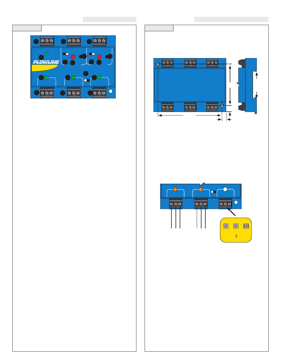
Step Five
GUIDE TO CONTROLS
INSTALLATION
1. Power indicator:
This green LED lights when AC power is ON.
2. Relay indicator:
This red LED will light whenever the con-
troller energizes the relay, in response to the proper condition at
the switch input and after the time delay.
3. AC Power terminals:
Connection of 120 VAC power to the
controller. The setting may be changed to 240 VAC if desired.
This requires changing internal jumpers; this is covered in the
Installation section of the manual. Polarity (neutral and hot) does
not matter.
4. Relay terminals (NC, C, NO):
Connect the device you wish to
control (pump, alarm etc.) to these terminals: supply to the
Common (COM) terminal, and the device to the Normally Open
(NO) or Normally Closed (NC) terminal as required. The
switched device should be a noninductive load of not more than
10 amps; for reactive loads the current must be derated or protec-
tion circuits used. When the red LED is ON and the relay is in the
energized state, the NO terminal will be closed and the NC termi-
nal will be open.
5. Time delay:
Use potentiometer to set delay from 0.15 to 60 sec-
onds. Delay occurs during switch make and switch break.
6. Input indicators
: Use these LEDs for indicating Flow or No-
Flow status of switch. For NC wiring, an Amber LED indicates
No-Flow and no LED indicates Flow. For NO wiring, an Amber
LED indicates Flow and no LED indicates No-Flow.
7. Invert switch:
This switch reverses the logic of the relay control
in response to the switch: conditions that used to energize the
relay will now de-energize the relay and vice versa.
8. Latch switch (LC82):
This switch determines how the relay
will be energized in response to the two sensor inputs. When
LATCH is OFF, the relay responds to switch Input 2A only; when
LATCH is ON, the relay will energize or de-energize only when
both switches (2A and 2B) are in the same condition (Flow or No-
Flow). The relay will remain latched until both switches change
conditions.
9. Input terminals:
Connect the switch wires to these terminals:
Note the polarity: (+) is a 24 VDC, 50 mA power supply (con-
nected to the red wire of a Flowline flow switch), and (-) is the
common ground path from the switch (connected to the black
wire). Also, the (S) is a 14 VDC, 25 mA supply (connected to the
white wire). If polarity between the red and black wires is
reversed, the switch will change from NC to NO.
Panel DIN Rail Mounting:
The controller may be mounted by either a back panel using two
screws through mounting holes located at the corners of the controller
or by snapping the controller on 35 mm DIN Rail.
Note:
Always install the controller in a location where it does not
come into contact with liquid.
Connecting N-channel Switches to Input Terminals:
Please note a difference between Flowline flow switches (N-channel,
P-channel and Relay). Use only the N-Channel or Relay switches
with the LC80 series of controller. Wire the Red wire to the (+) ter-
minal and the Black wire to the (-) terminal. Wire the White wire to
the (S). See the illustration below to indicate wiring for your switch.
Reversing Red and Black wire will change switch from NC to NO.
Note: connect the Shield wire on the Flow switch to the GND termi-
nal if required.
STANDARD
CONTROLLER
R E L A Y 1
R E L A Y 2
P O W E R
I N P U T 1
I N P U T 2 A
I N P U T 2 B
- +
- +
I N V E R T
D E L A Y
I N V E R T
D E L A Y
LATCH
ON OFF
1
3
7
2
5
4
4
7
2
5
6
8
6
6
9
9
9
I N P U T 1
I N P U T 2 A
I N P U T 2 B
LATCH
ON OFF
W
h
it
e
B
la
c
k
FT10-___2
GT10-___2
NC Wiring
R
e
d
W
h
it
e
R
e
d
FT10-___2
GT10-___2
NO Wiring
B
la
c
k
INPUT
24 VDC
100 mA
Max
( - )
S
( + )
14 VDC
25 mA
Max
3.475"
2.2"
.275"
.225"
3
5
m
m
D
IN
R
a
il