Wiring – Flowline LP50 Switch-Tek User Manual
Page 5
Step Six
Step Seven
WIRING
WIRING
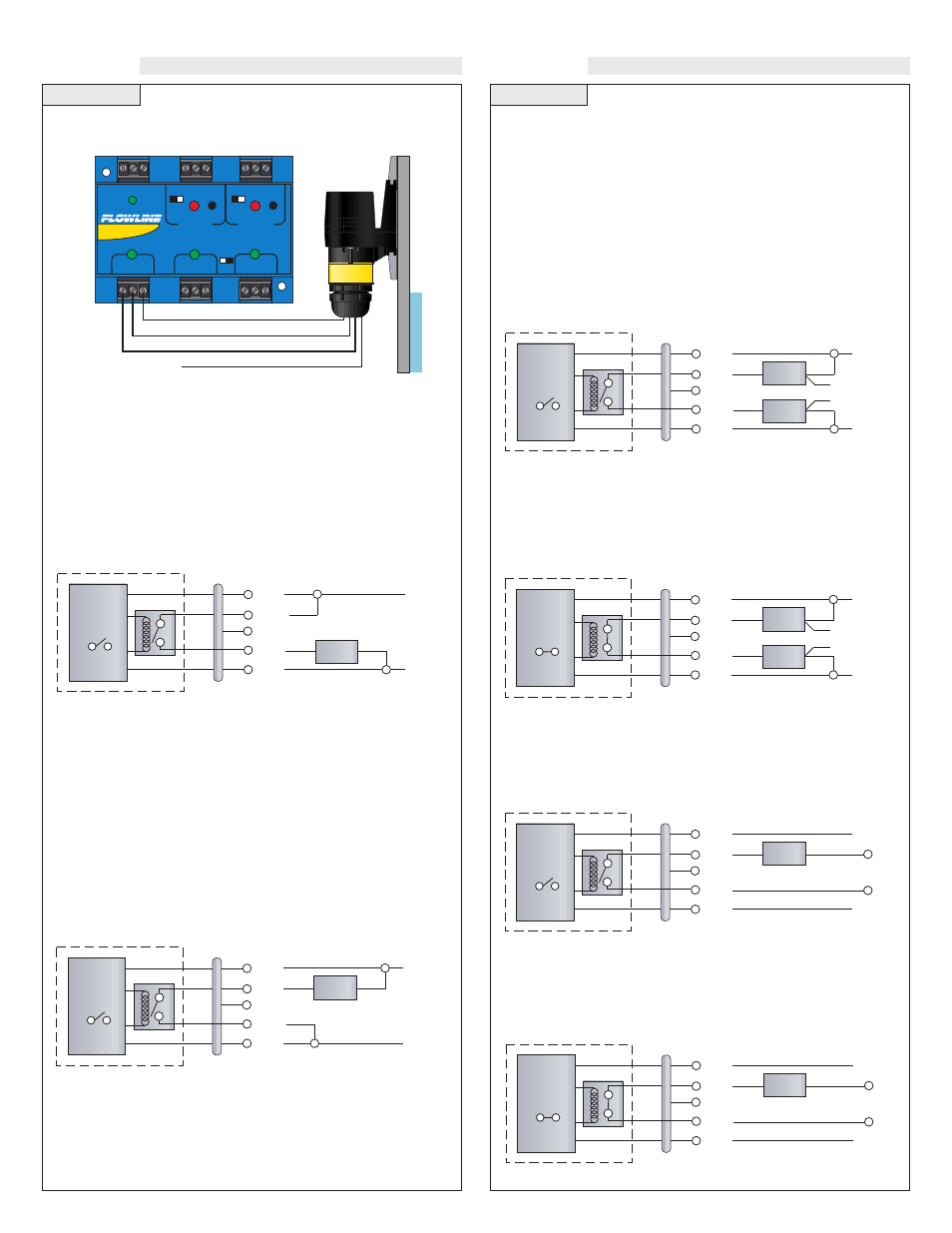
Wiring to a Flowline Controller
LC40 Series Controller:
STANDARD
CONTROLLER
R E L A Y 1
R E L A Y 2
P O W E R
I N P U T 1
I N P U T 2 A
I N P U T 2 B
- +
- +
I N V E R T
D E L A Y
I N V E R T
D E L A Y
LATCH
ON OFF
Black
Shield
White and Green - Not Used
Red
Wiring as a P-Channel or N-Channel output:
The LP50 Series can be substituted for either a P-Channel (PNP,
sourcing) output or a N-Channel (NPN, sinking) output.
Normally Open DC Load as a P-Channel Output:
To wire as a NO P-Channel output, follow the directions below. The
Red wire connects to Positive (+) of the power supply and the Black
wire connects to Negative (-). The Green wire is jumpered to the Red
wire while the White wire is connected to the LOAD. Jumper the
LOAD back to the Negative (-) to complete the circuit.
[Dry Condition]
Sensor
(NO)
RED
GRN
SHLD
WHT
BLK
LOAD
[+]
[-]
[Dry Condition]
Sensor
(NO)
RED
GRN
SHLD
WHT
BLK
LOAD
[+]
[-]
Normally Closed DC Load as a N-Channel Output:
To wire as a NC N-Channel output, follow the directions below. The
Black wire connects to Positive (+) of the power supply and the Red
wire connects to Negative (-). The White wire is jumpered to the Red
wire while the White wire is connected to the LOAD. Jumper the
LOAD back to the Positive (+) to complete the circuit.
Normally Open DC Load as a N-Channel Output:
To wire as a NO N-Channel output, follow the directions below. The
Red wire connects to Positive (+) of the power supply and the Black
wire connects to Negative (-). The White wire is jumpered to the
Black wire while the Green wire is connected to the LOAD. Jumper
the LOAD back to the Positive (+) to complete the circuit.
Normally Closed DC Load as a P-Channel Output:
To wire as a NC P-Channel output, follow the directions below. The
Black wire connects to Positive (+) of the power supply and the Red
wire connects to Negative (-). The Green wire is jumpered to the
Black wire while the White wire is connected to the LOAD. Jumper
the LOAD back to the Negative (-) to complete the circuit.
[Dry Condition]
Sensor
(NO)
RED
GRN
SHLD
WHT
BLK
LOAD
LOAD
OR
[+]
[-]
[Dry Condition]
Sensor
(NC)
BLK
GRN
SHLD
WHT
RED
LOAD
LOAD
OR
[+]
[-]
[AC Power]
[Dry Condition]
Sensor
(NO)
RED
GRN
SHLD
WHT
BLK
LOAD
[+]
[-]
[AC Power]
[Dry Condition]
Sensor
(NC)
BLK
GRN
SHLD
WHT
RED
LOAD
[+]
[-]
Wiring the Relay Output:
The Switch-Tek relay output can be wired as a dry contact to a VDC
or VAC power source. LP50 Series requires 12 - 36 VDC power to
operate the sensor and switch the relay. All illustrations below iden-
tify a Dry switch state as the normal position of the relay.
Switching a Normally Open DC Load:
The Red wire connects to Positive (+) of the power supply and the
Black wire connects to Negative (-). The LOAD can be attached to
either the Green or White wires. Complete the circuit by either con-
necting the Green to (+) VDC power or White to (-) VDC power (see
illustration below).
Switching a Normally Closed DC Load:
The Black wire connects to Positive (+) of the power supply and the
Red wire connects to Negative (-). The LOAD can be attached to
either the Green or White wires. Complete the circuit by either con-
necting the Green to (+) VDC power or White to (-) VDC power (see
illustration below).
Switching a Normally Open AC Load:
The Red wire connects to Positive (+) of the DC power supply and the
Black wire connects to Negative (-). The LOAD can be attached to
the Green wire and the Hot of the VAC power. Connect the White to
the Neutral of the VAC power (see illustration below).
Switching a Normally Closed AC Load:
The Black wire connects to Positive (+) of the DC power supply and
the Red wire connects to Negative (-). The LOAD can be attached to
the Green wire and the Hot of the VAC power. Connect the White to
the Neutral of the VAC power (see illustration below).