Specifications – Flowline LP50 Switch-Tek User Manual
Page 2
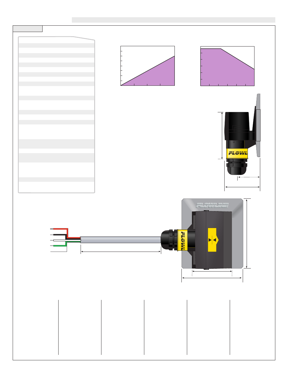
Step One
SPECIFICATIONS
Technology:
The non-intrusive RF capacitance switch detects the pres-
ence of liquid or air by measuring the conductive or dielec-
tric values which are present in all materials. An electrical
capacitor is formed between the level switch and the outer
tank wall. As liquid rises and falls against the inner wall, the
capacitance effect is greatly increased and the 1A SPST
relay changes state.
1.7"
(44mm)
2.8"
(71mm)
3.2"
(81mm)
8’ Cable
(2.5m)
(+)
(-)
NO/NC
COM
Shld
Red
RELAY
Black
White
Green
1.0"
(25mm)
1.6"
(41mm)
2
.2
"
(5
6
m
m
)
100
80
60
40
20
00
-20
12 16 20 24 28 32 36
Acceptable
Range
Unacceptable
Range
Maximum Tem. / Voltage Derating
Continuous 20 mA Sinking Curve
A
m
b
ie
n
t
S
e
n
s
o
r
T
e
m
p
e
ra
tu
re
(
¡C
)
Operating Voltage (VDC)
1,600
1,400
1,200
1,000
800
600
400
200
0
12 18 24 30 36
Acceptable
Range
Unacceptable
Range
4-20 mA Sensor
Electrical Loading Limits
M
a
x
.
S
e
ri
e
s
R
e
s
is
ta
n
c
e
(
O
h
m
s
)
Supply Voltage (VDC)
Tank mounting:
Non-intrusive
Tank mat. comp.:
Non-metallic
Tank wall thick.:
< 1" (25 mm)
Accuracy:
±
1 mm in water
Repeatability:
±
0.5 mm in water
Dielectric range:
> 10 constants
Conductive range: > 100 micromhos
Supply voltage:
12-36 VDC
Consumption:
25 mA maximum
Contact type:
(1) SPST relay
Contact rating:
120 VAC/VDC @ 1A
(CE: 60 VAC/VDC @ 1A)
Contact output:
Selectable NO/NC
Process temp.:
F: -40˚ to 176˚
C: -40˚ to 80˚
Enclosure rating:
NEMA 4X (IP65)
Enclosure mat.:
PSO
Conduit entrance: Single, 1/2" NPT
Bracket material:
1 0 0 5 : P P
5005: PVDF
6005: PE
Bracket mounting: 3M adhesive / plastic
thermal weld
Cable jacket mat.:
PP
Cable type:
4-conductor, #22 AWG
(shielded)
Cable length:
Standard: 10' (3m)
Special order: 25'
(7.6m) or 50' (15.2m)
Classification:
General purpose
CE compliance:
EN 61326 EMC
EN 61010-1 safety
Acetone
21
Acetoaldehyde
22.2
Acetyl methyl hexyl
ketone
28
Alcohol
16 to 31
Ammonia
15 to 25
Acetic acid
4.1 to 6.2
Butyl chloride
9.6
Barium chloride
9 to 11
Benzene
2.3
Benzine
2.3
Barium nitrate
5.6
Bromine
3.1
Chlorobenzene
4.7 to 6
Chlorotoluene
4.7
Chloroform
4.5 to 5.0
Chlorine, liquid
2.0
Carbon tetrachloride 2.2
Cyan
2.6
Cyclohexanemethanol 3.7
D.I. Water
20
Ethyl toluene
2.2
Ethyl alcohol
23
Ethylene glycol
37
Ethylene oxide
14
Ethylene dichloride
11 to 17
Ethylene chloride
10.5
Ethyl acetate
6.4
Ethyl salicylate
8.6
Ethyl stearate
2.9
Ethyl silicote
4.1
Formic acid
59
Ferric oleate
2.6
Freon
2.2
Glycerine
47
Glycol
30
Glycol nitrite
27
Gasoline
2 to 2.2
Hydrochloric acid
4.6
Isobutyric acid
2.7
Isobutyl methyl ketone
13
Jet fuel
1.7
Lead carbonate
18
Lead nitrate
38
Methyl salicylate
9.0
Methanol
33
Methyl alcohol 33 to 38
Margarine,liquid 2.8 to 3.2
Methyl acetate
7.3
N-butyl formate
2.4
Nitrobenzene
26 to 35
Nitrotoluene
25
Naphthalene
2.3 to 2.5
Oils, vegetable 2.5 to 3.5
Oils, mineral
2.3 to 2.4
Oils, petroleum 1.8 to 2.2
Oleic acid
2.5
Propane, liquid
1.8 to 1.9
Potassium nitrate
5.0 to 5.9
Potassium chloride
5.0
Stearic acid
2.3
Toluene
2.4
Trichloroethylene
3.4
Trichloroacetic acid
4.5
Terephthalic acid
1.5 to 1.7
Thinner
3.7
Urea
3.5
Vinyl chloride
2.8 to 6
Vinyl alcohol
1.8 to 2.0
Water, 20°C
80
Water, 100°C
48
Table of Common Dielectric Constants:
NOTE: Liquids with a conductivity value > 100 µU are fine if coating is not an issue. Liquids with a dielectric constant less than 20 may not be reli-
ably detected by an LP50 series level switch, depending on conditions.