Figure 2. direct mounting installation, Warning, Electrical installation instructions – Fill-Rite BD310 Series Fuel Transfer Pump User Manual
Page 2: Figure 3. typical island installation, Figure 4. wire diagram, Voltage selection switch
2
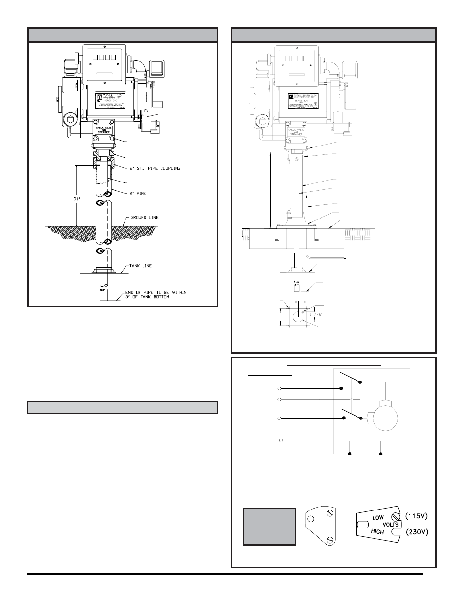
Figure 2. DIRECT MOUNTING INSTALLATION
1 1/2" SUCTION PIPE
LISTED
C
US
PUMP
300F7776 ADAPTER
JUNCTION BOX
1 1/2" SUCTION PIPE
ELECTRICAL CONDUIT
600F2130 PEDESTAL PIPE
300F7778 COUPLER
CONCRETE ISLAND 36" SQUARE
PUMP
END OF 1 1/2" OR LARGER SUCTION
PIPE MUST BE AT LEAST 3" OFF
TANK LINE
700F3060 PUMP BASE
32 1/2"
BOTTOM OF TANK
Figure 4. WIRE DIAGRAM
GROUND
GREEN
NEUTRAL
AUX.*
WHITE
BROWN
AC
BLACK
MOTOR
Series BD310
ELECTRICAL
CLEARANCE HOLE
7 25/32"
BASE ANCHOR BOLTS
LAYOUT FOR
1/2" BOLTS
FRONT
PUMP
4" DIA.
CONDUIT
1 7/8"
*
WARNING:
AUX. WIRE IS LIVE WIRE!
The AUX. lead wire is insulated and enclosed when shipped. Do
not connect this wire without first verifying the 'ON' line voltage of
the wire for compatibility to the equipment to be installed. Maximum
amperage on wire is 1 ampere. The wire must be insulated and
enclosed in the junction box if not used.
(pump shown
with meter kit
installed)
ISLAND INSTALLATION (see figure 3)
1. Install tank and piping per illustration.
2. The threaded 1-1/2" suction pipe is to extend 32-1/2" above
island.
3. Remove coupler from pedestal pipe by loosening set screws.
4. Slip pedestal pipe/pump base assembly over suction pipe.
5. Loosen screws in pump base to allow pedestal pipe to slide
down exposing end of suction pipe.
6. Screw coupler onto suction pipe.
7. Slide pedestal pipe into coupler, tighten set screws. Tighten
screws in pump base.
8. Mount pump on coupler.
ELECTRICAL INSTALLATION INSTRUCTIONS
1. Install pump as described in Mechanical Installation Instructions.
Read and understand all the electrical wiring
instructions before proceeding.
Pump motor voltage is factory set at 115 VAC. See figure 4 to
change voltage setting.
2. Remove pump's electrical junction box cover and straighten the
wires to make the stripped wire ends accessible outside of the
junction box.
WARNING: AUX. WIRE IS LIVE WIRE (see figure 4). The AUX.
lead wire (brown) is insulated and enclosed when shipped. Do
not connect this wire without first verifying the 'ON' line voltage
of the wire for compatibility to the equipment to be installed.
Maximum amperage on wire is 1 ampere. The wire must be
insulated and enclosed in the junction box if not used.
3. Power to the unit should be supplied from a dedicated 20 amp
circuit breaker. No other equipment should be powered from this
breaker. Threaded rigid conduit, seal fittings and conductor seal
(pump shown
with meter kit
installed)
Figure 3. TYPICAL ISLAND INSTALLATION
VOLTAGE
SELECTION
SWITCH
Voltage select screw should be placed next to
correct voltage setting (115 VAC shown)
1
1
5
23
0
OR