Video iris user circuit example, O iris lens. see, Video iris – ALLIED Vision Technologies Prosilica GS2450 User Manual
Page 35: User circuit example
Prosilica GS Technical Manual V2.0.5
35
Camera interfaces
Video iris user circuit example
Prosilica GS series cameras provide built-in auto iris controls for controlling
video-type auto-iris lenses. These lenses are available from many popular secu-
rity lens companies including Pentax, Fujinon, Tamron, Schneider and others.
Remote iris lens control allows the camera to be more adaptable to changing
light conditions. It allows the user to manually control the exposure and gain
values and rely solely on the auto iris for adjustment to ambient lighting.
Caution
The following schematic uses CAMERA POWER to power the
video iris lens, and assumes CAMERA POWER = 12 V. Most video
iris lenses operate at a 8–16 V input voltage. Therefore, this
circuit is not appropriate if using a 24 V camera power
supply. Doing so may irreparably damage your lens. Please
consult your video iris lens specifications for the appropriate
drive voltage.
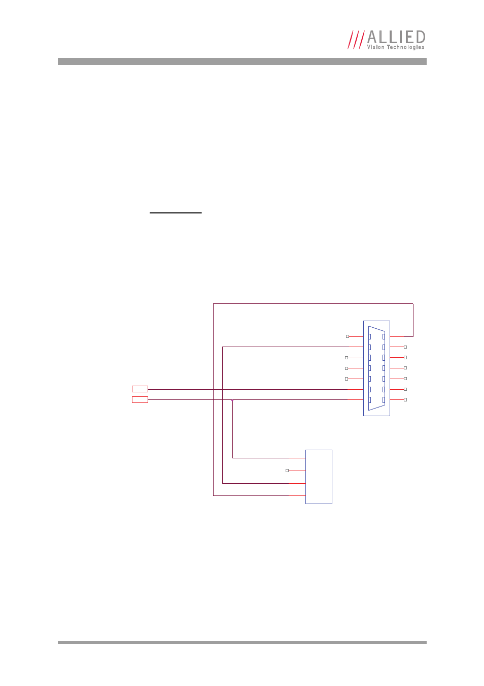
Figure 18: Prosilica GS video iris user circuit diagram
CABLE SIDE
CAMERA GND
3M10114-3000PE
1
2
3
4
5
6
7
8
9
10
11
12
13
14
CAMERA GND
CAMERA POWER
CAMERA POWER
1
2
3
4
LENS POWER
VIDEO SIGNAL
LENS GROUND
JEITA CONNECTOR