Sa nd – CHIEF ERSS36-42 User Manual
Page 6
ERSS
Installation Instructions
6
IMPORTANT ! : Depending on the mounting surface,
speaker size and mounting location, it may be advisable
to add sand to the center column to ensure a more stable
mount. Sand may also be added for acoustic decoupling
to reduce vibration noise. If neither of these are a
concern, proceed ahead to Step 13.
11. (Optional) Insert a large plastic bag into the open end of the
center column to line the interior.
12. (Optional) Pour sand or rock salt into the bag as desired or
until the bag is full. Leave enough room to tie a knot at the
top of the bag to keep sand from leaking. (See Figure 4)
Figure 4
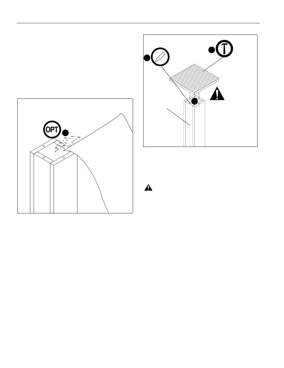
13. Fill the four holes on either end of the center column (A) half
full of wood glue. (See Figure 5)
IMPORTANT ! : Holes are not symmetrical! Bottom plate
must be installed with the wood grain finish in the
direction as shown in Figure 5!
14. Line up dowels (D) installed on top plate (B) with holes on
center column (A) and insert dowels into holes. (See Figure
5)
15. Use a hammer to gently tap dowels into holes. Place
another piece of wood on top of top plate to prevent hammer
marks. (See Figure 5)
16. Use the damp rag or cloth to wipe off any excess glue.
Figure 5
IMPORTANT ! : Wait at least one hour for the glue to
settle prior to applying any pressure to the unit.
17. Repeat steps for the other speaker stand.
WARNING:
Exceeding the weight capacity can result in
serious personal injury or damage to equipment! It is the
installer’s responsibility to make sure the combined weight of
all components located on top of each ERSS stand does not
exceed 25 lbs (11.34 kg). Use with products heavier than the
maximum weight indicated may result in instability or collapse
of the rack causing possible injury.
18. Install speakers to stands.
SA
ND
12
(B)
(A)
14
13
x 4
15
W
ood glue
must be installed
with wood grain
finish as shown