CHIEF LSTU User Manual
Page 7
Installation Instructions
LSTU
7
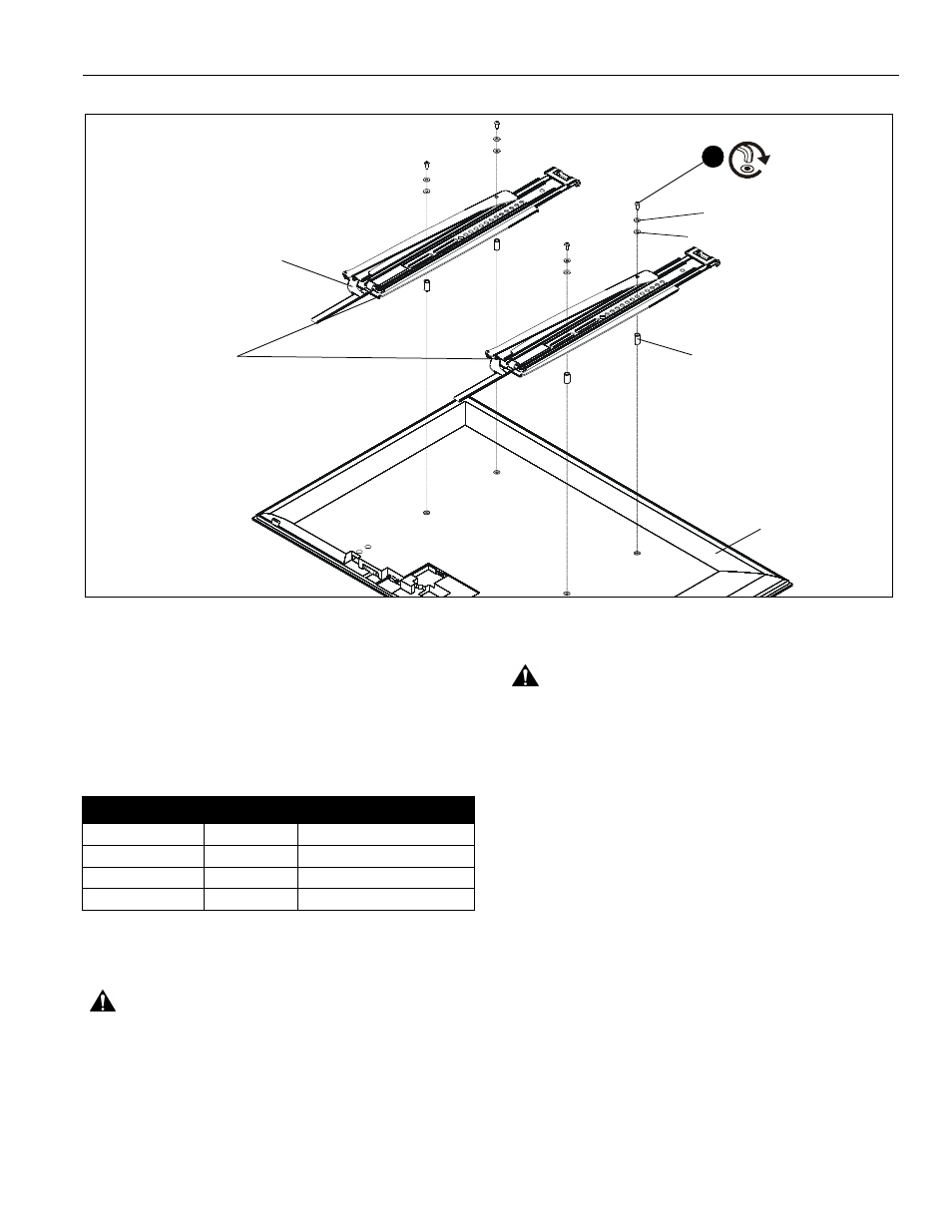
Figure 4
(B) x 2
5
(E-Q) x 4
(R) x 4 (if necessary)
(S or T) x 4 (if necessary)
(U or V) x 4 (if necessary)
Flag in open position
Display
3.
Determine which screws to use to connect interface
brackets to display. Use the screws that fit into the holes on
the back of the display. Make sure screws can make at least
three full turns into mounting holes. If not, select longer
screw from hardware kit.
4.
Determine which washers and shoulder washers to use with
the corresponding screw. Refer to table below for details.
5.
Install four button head cap screws (E - Q) through required
washers (R) and shoulder washers (S or T), interface
brackets (B), spacers (U or V) and into holes on back of
display. (See Figure 4)
WARNING:
IMPROPER INSTALLATION CAN LEAD TO
MOUNT FALLING CAUSING SEVERE PERSONAL INJURY
OR DAMAGE TO EQUIPMENT. Displays can weigh in
excess of 40 lbs (18.1 kg). ALWAYS use two people and
proper lifting techniques when installing display.
WARNING:
Exceeding the weight capacity can result in
serious personal injury or damage to equipment! It is the
installer’s responsibility to make sure the combined weight of
all components located between the LSTU up to (and
including) the display does not exceed 125 lbs (56.7 kg).
NOTE:
Make sure locking flags are in the open position before
attaching display to wall plate. Flags are shown in the
open position in Figure 4.
NOTE:
Display can be adjusted horizontally as long as guide
hooks are securely attached to wall plate.
IMPORTANT ! : If spacers are required, be sure to use
screws that are longer than the spacers but of the same
diameter!
6.
While supporting both sides of display, lift display up to the
wall plate on the wall.
Screw Size
Washers
Shoulder Washers
M4
use R
use S
M5
use R
use S
M6
none
use T
M8
none
none