Assembly and installation – CHIEF LSTU User Manual
Page 6
LSTU
Installation Instructions
6
Assembly And Installation
Wall Plate Installation Using Wood Studs
1.
Determine location for mount keeping in mind display size
and safety requirements.
2.
Use stud finder to locate studs. Wall plate can be mounted
on 2" x 4" wood studs either 16", 20" or 24" apart for double-
stud mounting. For triple-stud mounting, studs must be 16"
apart.
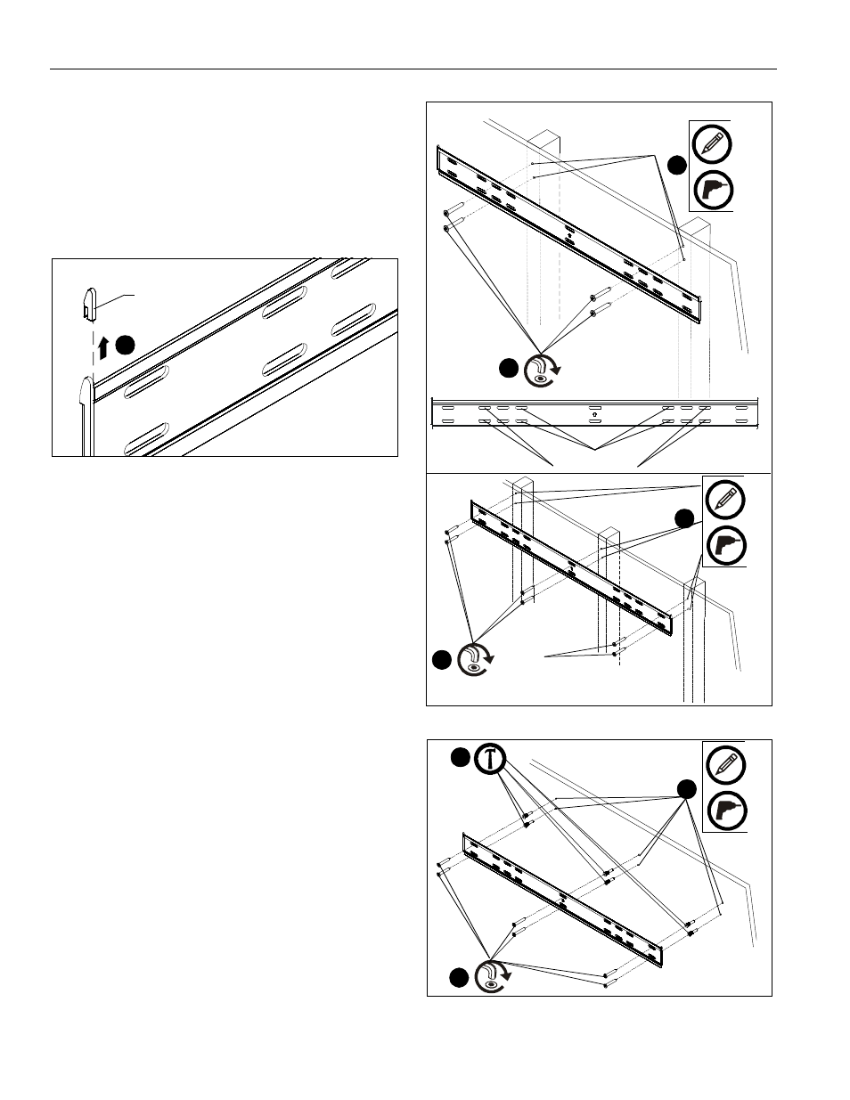
3.
Remove and discard two plastic shipping parts from the wall
plate (one from each end). (See Figure 1)
Figure 1
4.
Using wall plate as template, mark and then drill four or six
(for triple-stud mounting) 3/16" diameter pilot holes through
mounting surface, making sure the holes are centered in the
middle of each stud. Holes must be drilled at least 2-1/4"
deep. (See Figure 2)
5.
Install four or six connector screws (D) through wall plate
and into pilot holes using M4 Allen Head bit (C). (See
Figure 2)
Wall Plate Installation into Concrete or Concrete
Block
1.
Determine location for mount keeping in mind display size
and safety requirements.
2.
Using wall plate as a template, mark and then drill six 5/16"
diameter pilot holes through mounting surface. Use level to
make sure wall plate is perfectly horizontal. Holes must be
drilled at least 2-1/4" deep. (See Figure 3)
3.
Install six anchors (AA) into pilot holes drilled in Step 2. Use
a hammer to lightly tap anchors into holes. (See Figure 3)
4.
Install six connector screws (D) through wall plate holes and
into anchors. (See Figure 3)
Display Installation
1.
Lay display face side down on a level, non-abrasive
surface. Lay down a cloth if necessary to avoid scratching
the screen.
2.
Position two interface brackets (B) over holes in back of
display to determine which holes will be used for
installation.
NOTE:
Interface brackets should be positioned so that the
diamond hole in the bracket is located halfway between
the installation holes in order to ensure proper weight
distribution.
NOTE:
Spacers may not be required depending on the type of
display being mounted. They will typically only be used
with recessed or bump-out back screens.
NOTE:
Cable management pull straps should be easily
accessible underneath the display. Length of straps
can be adjusted if necessary.
Figure 2
Figure 3
Front of
wall plate
3
Shipping
part
(Double-stud mounting with studs 20" apart shown)
x 4
4
x 4
5
(D) x 4
holes for 16" studs
holes for 24" studs
(Triple-stud mounting)
x 6
4
x 6
5
(D) x 6
2
4
(D) x 6
3
(AA) x 6
x 6
x 6