CHIEF PDR Series User Manual
Page 7
Installation Instructions
PDR Series
7
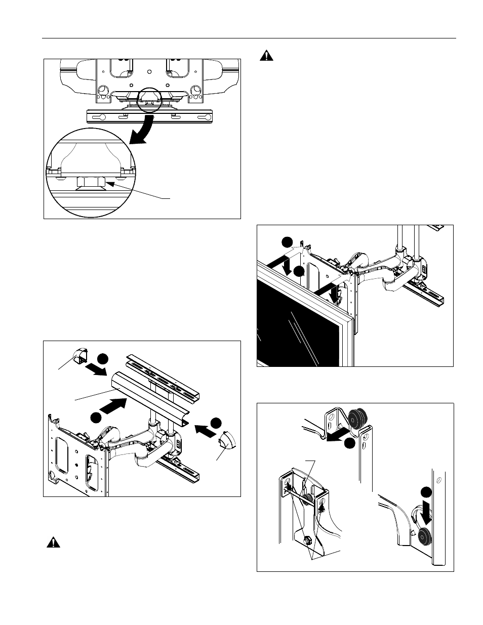
Figure 3
Installing Covers and End Caps
NOTE:
The covers and end caps have pressure fitting ends
that lock into place with each other.
1.
Install cover (B) over the top bracket. (See Figure 4)
2.
Install end caps (C and D) into the cover and top bracket.
(See Figure 4)
3.
Repeat Steps 1 and 2 for the lower mounting bracket. (See
Figure 4)
Figure 4
Mounting the Display
WARNING:
IMPROPER INSTALLATION CAN LEAD TO
MOUNT FALLING CAUSING SEVERE PERSONAL INJURY
OR DAMAGE TO EQUIPMENT. Displays can weigh in
excess of 40 lbs (18.1kg). ALWAYS use two people and
proper lifting techniques when installing display.
WARNING:
IMPROPER INSTALLATION CAN LEAD TO
MOUNT FALLING CAUSING SEVERE PERSONAL INJURY
OR DAMAGE TO EQUIPMENT. Make sure mounting buttons
on display are properly seated in mounting holes in faceplate.
1.
Move mount faceplate to extended position by grasping
faceplate and pulling outward away from wall.
2.
While supporting both sides of display, align four mounting
buttons on display or interface bracket with four mounting
holes in faceplate. (See Figure 5)
3.
Lower display into place listening for audible "click" to
ensure recessed area of mounting buttons are properly
seated in lower area of mounting holes and ClickConnect
mechanism has engaged. (See Figure 5) and
(See Figure 6)
NOTE:
Holes are provided in the faceplate for use with a
padlock or similar locking device, if desired. In addition,
the pin and nut may be removed from the upper holes
and moved to the lower holes for use as a more
permanent locking device. (See Figure 6)
Figure 5
Figure 6
Adjustment nut
1
2
2
(B)
(D)
(C)
2
3
3
2
A padlock or bolt may
be placed through latch
holes
To use as a
more permanent
lock, remove pin
and nuts and move
to lower holes.