CHIEF LTTU User Manual
Page 9
Installation Instructions
LTTU
9
Tilt Adjustment
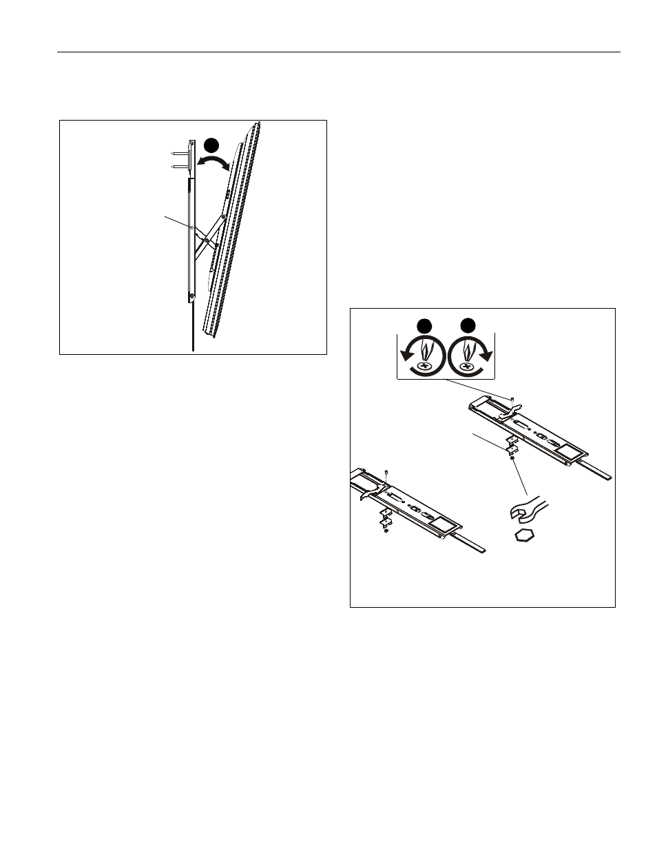
1.
Display may be tilted forward by pulling forward on the top
of the display as desired. (See Figure 7)
Figure 7
2.
Tilt tension is adjustable by using 3/16" hex key (AA) in the
tension adjustment nut. (See Figure 7)
NOTE:
Tension should be adjusted equally on each bracket to
ensure even tension distribution.
NOTE:
Due to the low profile of the Thinstall Series, certain
displays may have limited tilt capabilities.
3.
To return display to full vertical position, push display back
against wall until spring clips secure display in vertical
position.
Extra Spring Clip Installation (for larger displays)
IMPORTANT ! : Display should be held in vertical
position by spring clips. Listen for clicking sound when
returning display to the full vertical position. For larger
displays, a second spring clip (DD) may be added to
each upright so that the display can be held in the full
vertical position by these clips. Follow steps below to
install the extra spring clip.
1.
Remove display and attached uprights from wall plate (A) to
gain access to spring clip screws.
2.
Pull out display from uprights to expose existing spring
clips.
3.
Remove hex nuts and screws holding spring clips to
uprights. (See Figure 8)
4.
Use removed hex nuts and screws to install additional
spring clips (DD) along with removed spring clips onto
uprights. (See Figure 8)
Figure 8
tension adjustment nut
(located inside hole)
1
Side View
display not shown for clarity
(DD) x 2
3
4