CHIEF LTTU User Manual
Page 7
Installation Instructions
LTTU
7
Wall Plate Installation into Concrete, Concrete
Block or Brick
WARNING:
INSTALLING THE LTTU INTO UNDERRATED
OR DAMAGED CONCRETE CAN LEAD TO SERIOUS
INJURY OR DAMAGE TO PRODUCT! When installing into
concrete, only install the LTTU into concrete at least 8" in
depth or into 8"x8"x16" concrete blocks! Never install the
LTTU into cracked, chipped or flaking concrete.
1.
Determine location for mount keeping in mind display size
and safety requirements.
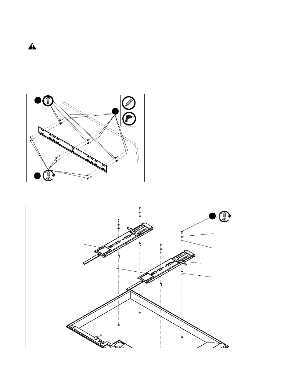
Figure 3
2.
Using wall plate as a template, mark and then drill six 5/16"
diameter pilot holes through mounting surface. Use level to
make sure wall plate is perfectly horizontal. Holes must be
drilled at least 2-1/4" deep. (See Figure 3)
3.
Install six anchors (BB) into pilot holes drilled in Step 2. Use
a hammer to lightly tap anchors into holes. (See Figure 3)
4.
Install six connector screws (D) through wall plate holes and
into anchors. (See Figure 3)
Display Installation
1.
Lay display face side down on a level, non-abrasive
surface. Lay down a cloth if necessary to avoid scratching
the screen.
2.
Position left and right interface brackets (B and C) over
holes in back of display to determine which holes will be
used for installation. (See Figure 4)
NOTE:
Interface brackets should be positioned so that the
diamond hole in the bracket is located halfway between
the installation holes in order to ensure proper weight
distribution. Brackets may need to be expanded to tilt
position in order to expose installation holes.
NOTE:
Cable management pull straps should be easily
accessible underneath the display. Length of straps
can be adjusted if necessary.
NOTE:
Spacers may not be required depending on the type of
display being mounted. They will typically only be used
with recessed or bump-out back screens.
2
4
(D) x 6
3
(BB) x 6
x 6
x 6
Figure 4
5
(E-Q) x 4
(R) x 4 (if necessary)
(S or T) x 4 (if necessary)
(U or V) x 4 (if necessary)
(B)
(C)
locking flag in open position