Adjustments – CHIEF FHS Series User Manual
Page 5
Installation Instructions
FHS Series
5
WARNING:
IMPROPER INSTALLATION CAN LEAD TO
DISPLAY FALLING CAUSING SERIOUS PERSONAL
INJURY OR DAMAGE TO EQUIPMENT! Using screws of
improper size may damage your display. Properly sized
screws will easily and completely thread into display
mounting holes. If spacers are required, be sure to use longer
screws of the same diameter.
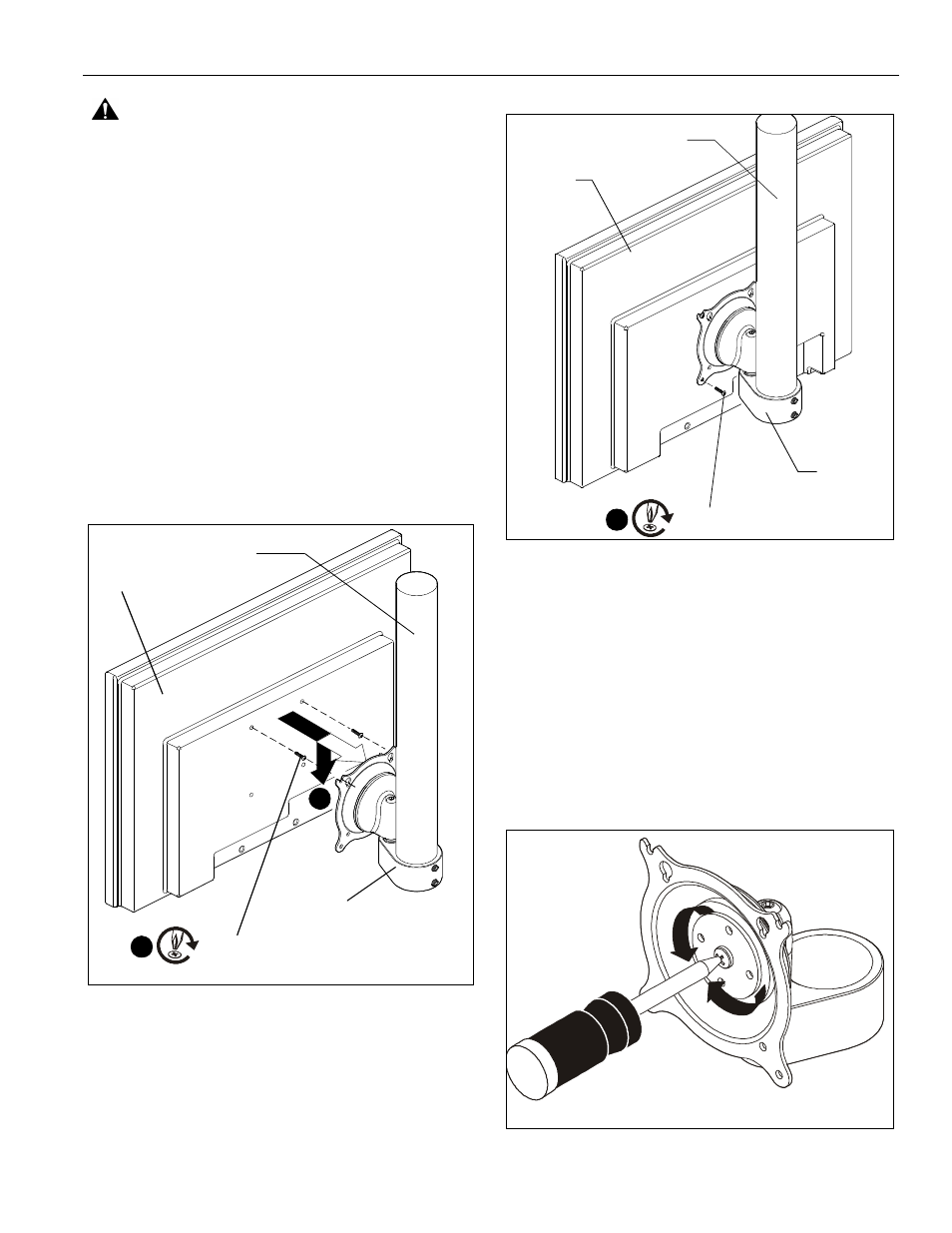
3.
Install two Phillips pan head machine screws (A, B, or C)
into upper mounting holes in display back leaving 3/16" of
screw protruding out of display.
4.
Align screws in display back with upper mounting holes in
Centris cup and lower display until screws are seated in
lower area of mounting slots (100 x 100) or teardrop
mounting holes (75 x 75).
5.
Hold display so that display back is against Centris cup and
install two Phillips pan head machine screws (A, B, or C)
through lower mounting holes in Centris cup and into lower
mounting holes in display back.
NOTE:
If the display has a recessed mounting surface,
spacers (D or E) must be placed between display back
and Centris cup and longer screws must be used to
secure display.
Figure 4
6.
Route cables and wires to display.
Figure 5
ADJUSTMENTS
To adjust display Roll, Pitch, and YAW tension:
1.
Disconnect all wires and cable from the display.
2.
Remove two Lower screws securing display to Centris cup.
3.
Loosen two Upper screws securing display.
4.
Lift display upward and away from mount.
5.
Using a Phillips screwdriver turn the tension adjustment
screw clockwise to increase tension, or counter-clockwise
to decrease tension. (See Figure )
6.
Re-install display.
Figure 6
4
(A, B, or C) x 2
3
(A)
Display
Extension column
(not included)
(A, B, or C) x 2
5
(A)
Display
Extension column
(not included)