Installation – CHIEF FHS Series User Manual
Page 4
FHS Series
Installation Instructions
4
INSTALLATION
IMPORTANT ! :
These installation instructions assume that a
1-1/2" NPT or NPSM following ANSI/ASME B1.20.1 (Schedule
40, 0.154" minimum thickness steel or aluminum - ASTM B221)
threaded extension column (not included) has been properly
installed and is in place.
1.
Thread FHS assembly (A) onto 1-1/2" NPT or NPSM
following ANSI/ASME B1.20.1 (Schedule 40, 0.154"
minimum thickness steel or aluminum - ASTM B221)
threaded extension column until hand tight, with a minimum
of four threads engaged.
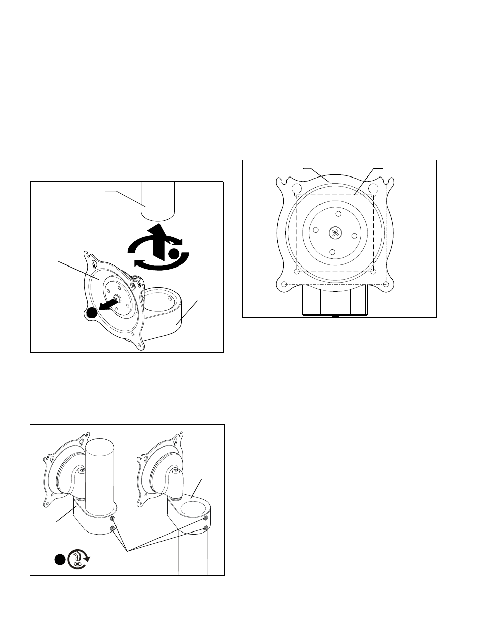
2.
Adjust FHS assembly (A) position until Centris cup is facing
the desired position of the display. (See Figure 1)
Figure 1
3.
When FHS assembly (A) is properly positioned secure to
1-1/2" NPT pipe by installing and tightening 5/16-18 x 3/8"
set screw (F) using 3/16" hex wrench (H). (See Figure 2)
NOTE:
If mount is being used to couple two pipes, use both set
screws when securing mount (A) to pipes.
Figure 2
Display Installation
1.
Determine mounting pattern on display. (See Figure 3)
NOTE:
The mount is designed to accommodate both 75 x 75
and 100 x 100 VESA mounting patterns. If the display
being mounted has either of these mounting patterns
proceed to Step 3.
NOTE:
If the display does NOT have a 75 x75 or 100 x 100
VESA mounting pattern, an interface bracket will be
required. The FHSV mount comes with a 200 x 100
interface bracket (J). Proceed to Step 2.
Figure 3
2.
(200 x 100 Mounting Pattern ONLY) Install FSA4101
interface bracket (J), if required, following the instructions
provided with the interface bracket kit. Proceed to Step 3.
1
Centris Cup
(A)
Extension column
(not included)
2
(A)
(A)
3
(F) x 1 [(F) x 2 to couple
two pipes]
VESA 100 x 100
VESA 75 x 75