CHIEF TPM-2000 Series User Manual
Page 5
Installation Instructions
Model: TPM-2000
5
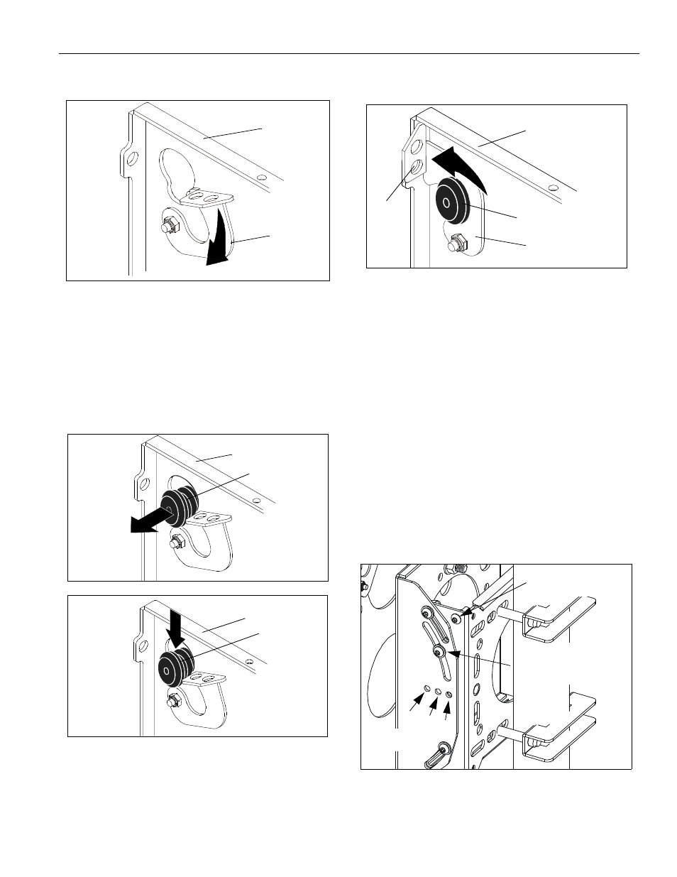
1.
Rotate Q-Latch to the OPEN position (see Figure 6).
Figure 6: Open Q-Latch
2.
Lift and maneuver display such that all mounting
buttons fit into button openings on faceplate. Lower
display firmly into place. Ensure each button has fully
seated in its button opening (see Figure 7).
NOTE: If Q-Latch does not fully engage, ensure the
mounting buttons are fully seated in the button
openings.
Figure 7: Align Display
3.
Rotate Q-Latch to the CLOSED position (see Figure
8).
NOTE: A hole is provided in the Q-Latch and faceplate to
accommodate the insertion of a padlock or similar
locking device.
Figure 8: Close Q-Latch
4.
Attach all cables to display.
ADJUSTMENTS
Pitch (Tilt) Adjustment
1.
Loosen right and left pitch adjustment screws (see
Figure 9).
2.
Position display to desired angle.
3.
Tighten pitch adjustment screws (see Figure 9).
•
The display may be locked at any position
between 5° tilt up and 15° tilt down by tightening
the pitch adjustment screws.
However, if additional locking security is desired,
use key (20) and a 7/16" wrench to remove the
locking screw(s) from the stored location(s) and
install into the 0°, 5°, or 10° pitch lock hole(s).
Figure 9: Pitch Adjustment
Faceplate
OPEN
Q-Latch
Faceplate
Mounting
Button
Faceplate
Mounting
Button
Faceplate
Q-Latch
Mounting
Button
Insert
padlock
here
(optional)
Pitch Adjustment Screw
(right side shown; left
side similar)
0°
5°
10°
Locking Screw
(stored location)
Pitch Lock Holes
(optional)