CHIEF FDP Series User Manual
Page 7
Installation Instructions
FDP Series
7
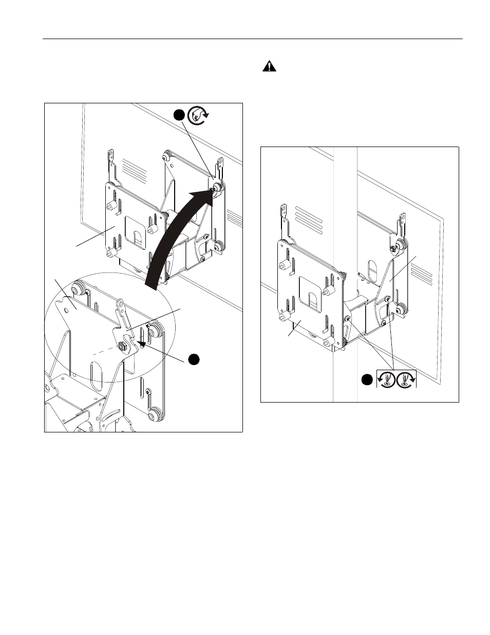
3.
Lift and maneuver display so that mounting buttons on
interface brackets (F) fit into button openings on FDP (A).
(See Figure 7)
4.
Lower display firmly into place. Ensure each button has fully
seated in its button opening.
Figure 7
5.
Engage latching flags, locking the flat panel displays
attached to interface brackets (F) in place (See Figure 7).
Tilt Adjustment
WARNING:
IMPROPER HANDLING CAN LEAD TO
DISPLAY FALLING CAUSING SERIOUS PERSONAL
INJURY OR DAMAGE TO EQUIPMENT! Inadequate support
of display while adjusting tilt may cause display to fall!
1.
Adjust tilt by loosening (slightly) tilt adjustment screws on
each side of FDP (A), adjust to desired angle, then tighten
tilt adjustment screws. (See Figure 8)
Figure 8
(Pole not shown
for clarity)
(A) x 2
(button opening)
Unlocked
(F) x 2
3
5
Locked
2
(Display)
1
(Tilt adjustment screws)
(F) x 2
(A) x 2
- MSMVPU (12 pages)
- K-Series (16 pages)
- FSP Series (8 pages)
- JPP Series (8 pages)
- TPP Series (12 pages)
- TPM-2000 Series (8 pages)
- TPS Series (12 pages)
- PSS Series (8 pages)
- FSB018BLK (2 pages)
- PTS Series (8 pages)
- STS1 (8 pages)
- STLU (12 pages)
- MSS6000 (12 pages)
- PXR (32 pages)
- CM2L40 (76 pages)
- CM2C40 (76 pages)
- FWDIW Series (8 pages)
- JWDIW Series (8 pages)
- MWRIW Series (12 pages)
- PWRIW Series (12 pages)
- PNRIW Series (12 pages)
- TS525TU (16 pages)
- TS325TU (20 pages)
- TS218SU (16 pages)
- TS118SU (12 pages)
- MCD Series (8 pages)
- PDC Series (8 pages)
- MCS Series (8 pages)
- PCM Series (8 pages)
- PCS Series (8 pages)
- FHP110, FHPV (8 pages)
- JHS Series (8 pages)
- FHS Series (8 pages)
- MCB1U (12 pages)
- MCM1U (12 pages)
- MWC Series (8 pages)
- PWC-2000 (12 pages)
- RMT2 (12 pages)
- MTTU (12 pages)
- LTTU (12 pages)
- FTR Series (8 pages)
- MTMPU (12 pages)
- LTMPU (12 pages)
- XSM Series (12 pages)