Installing display with interface bracket – CHIEF FDP Series User Manual
Page 6
FDP Series
Installation Instructions
6
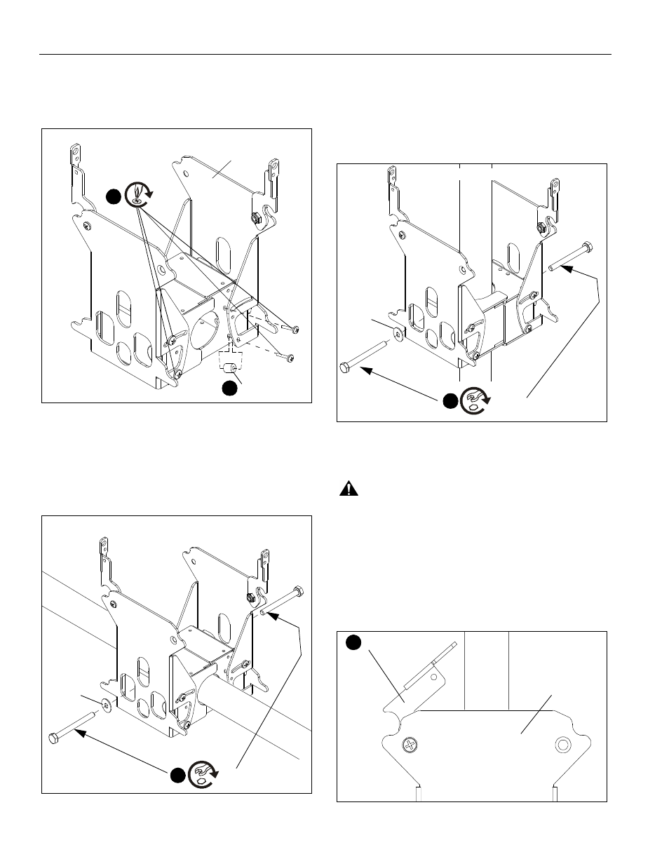
4.
Insert 1/2" x .194 x 1/2" nylon spacers (C). (See Figure 3)
5.
Secure to FDP (A) using 10-24 x 1" Phillips head screws
(B). (See Figure 3)
Figure 3
6.
Assemble two FDP bracket halves (A) around pole for
horizontal mounting. (See Figure 4)
7.
Insert two 1/4-20 x 4-1/4" hex bolts (D) and two
.75 x .26 x .048" spacers (E), then tighten to secure
the two bracket halves against pole. (See Figure 4)
Figure 4
Vertical Installation
The FDP assembly ships configured for vertical pole
mounting.
1.
Assemble two FDP bracket halves (A) and secure around
pole using two 1/4-20 x 4-1/4" hex bolts (D) and two .75 x
.26 x .048" spacers (E). (See Figure 5)
Figure 5
Installing Display with Interface Bracket
WARNING:
Exceeding the weight capacity can result in
serious personal injury or damage to equipment! It is the
installer’s responsibility to make sure the combined weight of
all components attached to the FDP does not exceed 45 lbs
(20.4 kg).
1.
Install FSB interface bracket (F) using the instructions and
hardware provided with the interface bracket kit.
2.
Make sure both latching flags on FDP are in the unlocked
position. (See Figure 6)
Figure 6
(B) x 8
5
(C) x 8
4
(A) x 2
Horizontal Configuration
Horizontal Configuration
(D) x 2
7
(E) x 2
(E) x 2
Vertical Configuration
(D) x 2
1
Unlocked
(A) X 2
2