Tr-a/tr-v – CEMB USA TR-V User Manual
Page 2
TR-A/TR-V
The TR-A and TR-V transmitters can be installed directly in the field inside an IP65 container (junction box) or on the rear of
the panel inside an electric control panel. We recommend you use this connection method whenever you want to monitor
machines situated in classified areas (in the chemicals or petroleum industries), using intrinsecally safe transducers that
interface with the transmitters installed in the safe area via a Zener barrier situated near the transmitter.
Main features
• type of transducer (velocimeter or accelerometer)
• dimension measured (displacement, velocity, acceleration)
• means of detection (RMS, peak, peak-to-peak)
• measuring range
• high pass filter
• low pass filter
• two or three wire power supply
Presettings possible when ordering
The TR-A and TR-V transmitters measure the absolute vibration of the pedestal of any rotating machine capable of interfacing
directly with a two-wire technique acquisition system (4-20 mA current loop) or a three-wire technique acquisition system (24
V DC power supply).
Function
The need to monitor an increasing number of machines at a reasonable cost, especially in large plants, calls for compact
systems that are easy to install and interface with the centralized data acquisition system. The TR-A and TR-V transmitters
minimize the proportion of the installation and cabling costs, which normally limits the possibilities of applying conventional
vibration monitoring systems.
These transmitters acquire the signal of a velocimeter or an accelerometer and convert it into a signal in current (4-20 mA) proportional
respectively to the displacement or to the velocity of the vibration in the first case and to the velocity or to the acceleration of the vibration in
the second case. The transmitter is connected to the sensor (veloc imeter or accelerometer) via a shielded bipolar cable (2x1 mm
2
).
The transmitter is connected to the acquisition system via a bipolar cable (2x1 mm
2
) or a tripolar cable (3x1 mm
2
).
A BNC socket can be used to connect a spectrum analyser so that the signal can be analysed and the machine being monitored can
be diagnosed.
Typical applications
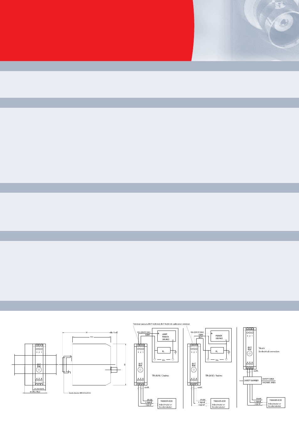
Overall dimensions, installation and elettrical connection