4 • wiring the fan – Hunter 23949 48 Forest Hill User Manual
Page 9
9
42693-01 • 05/14/10 • Hunter Fan Company
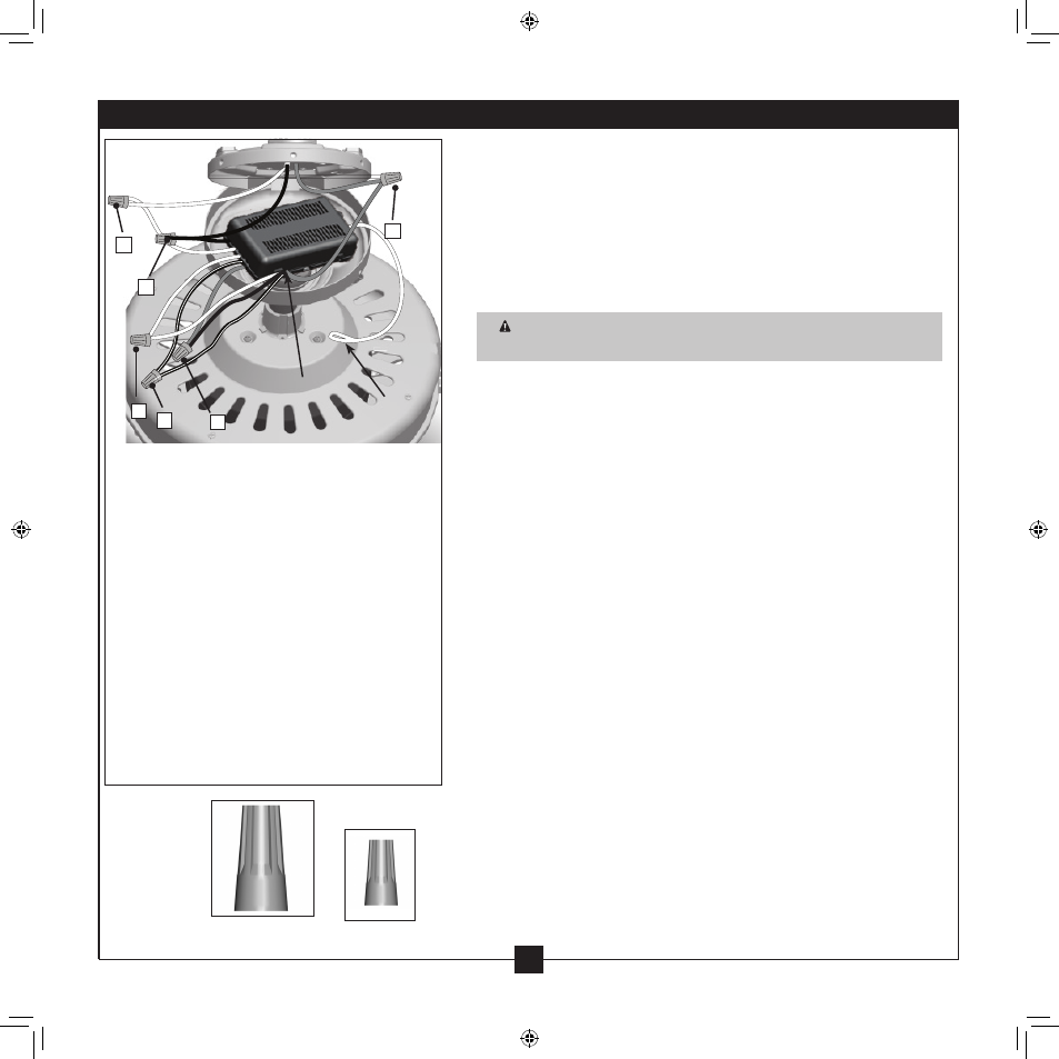
Step 4-3
A • Ground/Green
Step 4-4
B • Ceiling Black
• Receiver Black: “LIVE IN”
C • Ceiling White
• Receiver White: “NEUTRAL IN”
Step 4-5
D • Fan Black/White
• Receiver Black/White: “LIGHT OUT”
E • Fan Black
• Receiver Red: “FAN OUT”
F • Receiver White: “COMMON OUT”
• Fan White
All wiring must be in accordance with national and local electrical
codes and ANSI/NFPA 70. If you are unfamiliar with wiring, use a
qualified electrician.
4-1 . Make sure the power is still off .
4-2 . To connect the wires, hold the bare metal leads together and place
a wire connector over them, then twist clockwise until tight . For
all these connections use the wire connectors provided .
CAUTION: Be sure no bare wire or wire strands are visible after
making connections .
4-3 . Connect the ground wire from the ceiling to the green ground
wire from the ceiling plate and the green ground wire from the
downrod or low profile washer .
4-4 . Using the large wire connector, connect the white wires and the
black wires from the ceiling as follows:
• The white (common) power wire from the ceiling to the white
wire from the receiver (marked on red tag “NEUTRAL IN”)
• The black power wire from the ceiling to the black wire from
the receiver (marked on white tag “LIVE IN”)
4-5 . Using the small wire connector, connect the wires from the fan as
follows:
• The black wire from the fan to the red wire from the receiver
(marked on red tag “FAN OUT”)
• The white wire from the fan to the white wire from the receiver
(marked on white tag “COMMON OUT”)
• The black/white wire from the fan to the black/white wire from
the receiver (marked on white tag “LIGHT OUT”)
4-6 . Check each connection to make sure no bare wire or wire strands
are visible . Push all wires and wire connectors back through the
ceiling plate hole into the outlet box .
4-7 . Run the white antenna wire from the receiver around the inside of
the canopy for clear reception .
Large Wire
Connector
Steps 4-3 – 4-7
Small Wire
Connector
Receiver
A
B
C
E
F
D
Antennae
4 • Wiring the Fan