J&M 1384S Running Gear User Manual
Page 7
Pg. 7
SAFETY SIGNS
IMPORTANT: Install new safety signs if the old signs are destroyed, lost, painted over or cannot be read.
When parts are replaced that have safety signs, make sure you install a new sign with each new part.
New signs are available from the manufacturer or your authorized dealer.
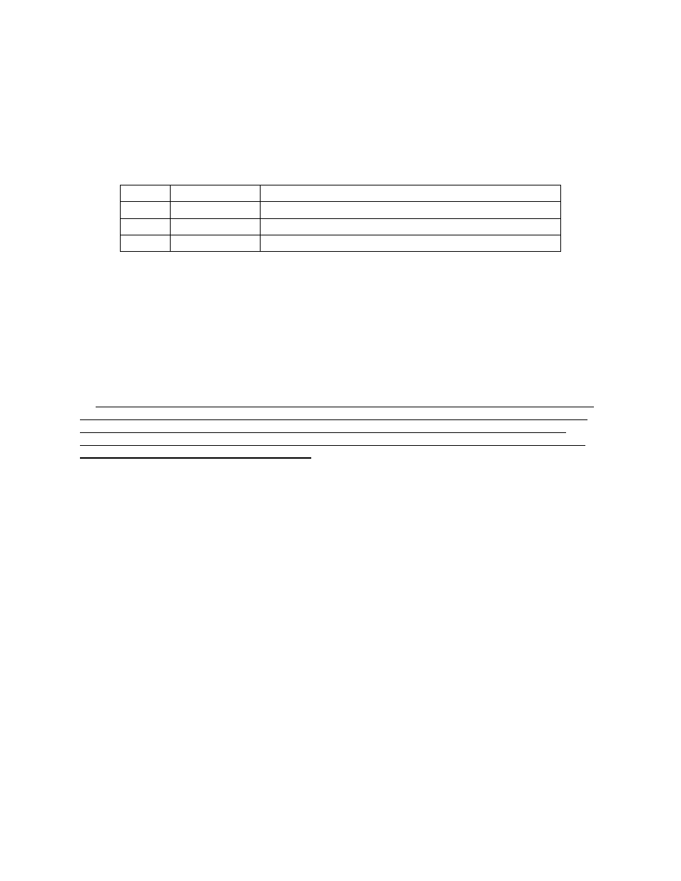
DECAL PARTS LIST
Item #
Part #
Description
1
DC-111
Caution: Keep Lug Nuts Tight
2
DC-113
Caution: Check Fluid Level
3
DI-114M
J&M Oval - Medium
SET-UP INSTRUCTIONS
IMPORTANT: Set-up work to be performed by qualified servicemen only.
1. Mount tires on the wheels and inflate per tire manufacturer’s recommendations and instructions. When
using 22.5x8 ¼ wheels, mount the wheel with the offset inward, valve stem outward. This will make the
tread width 82” (center of wheel to center of wheel) and allow clearance between tire and the frame when
turning.
2. Mount the tires to the hubs and tighten the tapered hub nuts to 100 ft. lb. torque or the flat hub nuts to
100 ft. lb. torque . Check the hub nuts after the first hour of operation, then every 10 hours of operation
for the first 40 hours of use. These nuts must be kept tight at all times. Wheels that are improperly
installed on the running gear, resulting in product failure, will nullify the warranty and shift the burden of
liability to the owner/operator of the equipment.
3. Slide the coupling pole into the front and back assemblies, slipping the collar in the back assembly.
When mounting to a 385SD Gravity Wagon, the spacing on the coupling pole (approximate distance
between holes on the coupling pole) should be 24” (Measured between the closest two bolts). The
distance from the center of axle to center of axle is approximately 104”.
4. Fasten the tongue to the front of the assembly using the tongue bolt and hex nuts. Attach the tongue
springs to the brackets on the tongue and hitch assembly. Check underneath the tongue and make sure
the 7/8” x 2 ¼” bolt with spacer is secure.
5. Mounting Brake Lines to Running Gear with Hydraulic Drum Brakes. IMPORTANT: Running Gears
with Hydraulic Brakes should be set up immediately after delivery from factory to prevent dirt and
moisture from entering the brake system. Mount the brakes lines from the rear of the master cylinder to
the Drum Brakes according to the Tongue Assembly and Brake Lines and Fittings drawing located in the
Repair Parts Section of this manual. Be careful not to over tighten the fittings and strip the threads. Use
care in shaping brake lines to avoid sharp bends or kinks. Be sure to use a “Double-Flaring” type of tool
on steel tubing to assure tight leak proof connections. Be sure and use hydraulic rubber hoses at points
of flexing. Anchor hose ends to avoid stress on tubing. Always use DOT 5 Silicone Brake Fluid or
equivalent.