J&M 1000-20S User Manual
Page 25
23
NOTE: When inserting both the weigh spindles or the hitch weigh bar, be sure that the TOP of the spindle is in the up-
right position as indicated by the decal on each weigh bar. Failure to correctly align the weigh bar and spindles in the
upright position will cause the scale system to read with greater inaccuracy.
To connect the Power Cord to the Indicator Box, attach screw plug end of the Power Cord into the power port
of the Indicator Box. To connect to the battery, secure the Red Wire of the Power Cord to the Positive Terminal
of the battery and the Black Wire to the Negative Terminal. Be sure any additional wires provided by the Power
Cord are properly stored and secured.
CONNECTING THE POWER CORD
1.
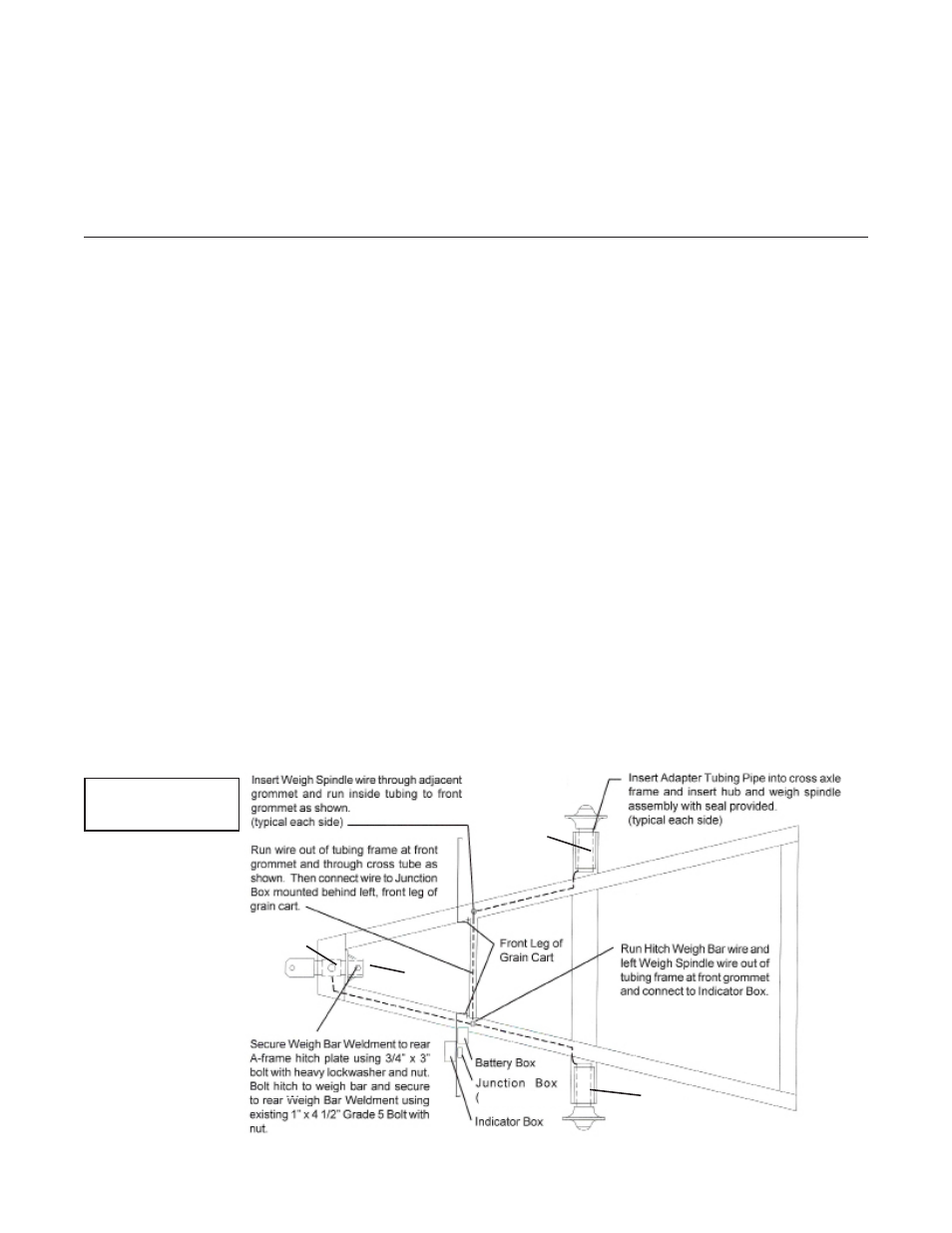
Installation of Scale System
for Single Wheel for Models 1000, 1050, 1051, 1150, 1151, 1325 or 1326
Model 1325 or 1326 Equipped with Dual Wheels or Grain Carts Equipped with Tracks
PARTS LIST (Weigh-Tronix)
(for Models 1000, 1050,
1051, 1150, 1151, 1325 or 1326 with Single Wheels and
Models 1325 or 1326 with Dual Wheels)
#
1
1
2
3
3
4
4
5
6
7
8
9
10
11
12
13
14
15
16
Part #
450WTS
55WS
278WB
640
915
JB-3
JB-5
PC-2
-------
-------
ATP-55
MBI-2
WBW-278
BB-2
343BWN
MB-58612
MB-381
-------
MB-1434
Description
4 1/2” Weigh Spindle (for 1000-20S and
1325-dual wheel grain carts)
5 1/2” Weigh Spindle (1050, 1150 and 1325
single wheel grain carts)
2 7/8” Hitch Weigh Bar
640 Indicator
915 Indicator
3-Pt Junction Box (single wheel)
5-Pt Junction Box (1325-D)
Power Cord to Battery
---------------
---------------
6” OD Adapter Pipe Tubing (for single wheel
carts)
Mounting Bracket for Indicator
2 7/8” Weigh Bar Weldment
Battery Box with Strap
3/4” x 3” Bolt (Gr 8) with Heavy Lock
Washer and Nut
5/8” x 6 1/2” Bolt (Gr 5) with Nut
3/8” x 1” Bolt with Nut
----------------
1/4” x 3/4” Bolt with Nut
PARTS LIST
(Digi-Star) (for track carts or Models 1050,
1051, 1150 and 1151 with dual wheels)
#
1
2
3
4
5
6
7
8
9
10
11
12
13
14
15
16
Part #
375WS
278WB-T
EZ-400L
JB-5
PC-1
ECI-1
37605SA
ATP-375-GS
MBI-1
WBW-278T
BB-2
343BWN
MB-58612
MB-381
PB-10
141837
Description
3 3/4” Dia. Weigh Spindle
2 7/8” Weigh Bar
Indicator Box
Junction Box (5 pt.)
Power Cord to Battery
Extension Cord (optional)
Seal (Hub)
4 1/2” OD Adapter Pipe Tubing
Mounting Bracket for Indicator
2 7/8” Weigh Bar Weldment
Battery Box with strap
3/4” x 3” Bolt (Gr 8) with Heavy Lock
Washer and Nut
5/8” x 6 1/2” Bolt (Gr 5) with Nut
3/8” x 1” Bolt with Nut
#10 Pan Bolt with Nut
30 ft. Standard Cable for J-Box to Indicator
Single Wheel
Layout Diagram
1
1
2
10
3
11