J&M 1000-20S User Manual
Page 24
22
Using the Junction Box as a template, mark and drill
holes on the inside face of the front left side leg of the
grain cart. The Junction Box should be positioned ap-
proximately 23” above the tubing of the A-Frame.
After the holes have been drilled, secure the Junction
Box to the inside of the front left leg of the grain cart
using four #10 bolts and nuts.
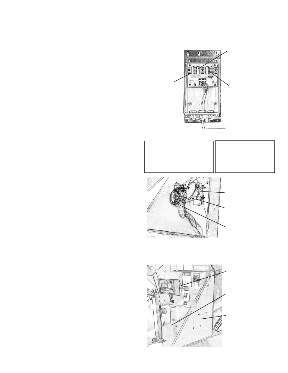
Remove the cover from the Junction Box. Insert the
Hitch Weigh Bar wire through the center port and
connect to the center terminal of the Junction Box by
matching the colored wires. Repeat for the left and
right side weigh spindle wires.
Connect the J-Box cable between the center terminal
and the indicator located on the front of the grain
cart leg.
Replace cover on Junction Box
MOUNTING THE JUNCTION BOX
1.
2.
3.
4.
5.
Use Junction Box as a template to drill holes on
inside face of front grain cart leg.
Run Wire from
Right Weigh
Spindle through
right port and
connect to right
side terminal.
Run Wire
from Left
Weigh Spindle
through left
port and con-
nect to left side
terminal.
Run Wire from
Hitch Weigh Bar
through center
port and con-
nect to center
terminal.
Connect the
J-Box cable be-
tween the center
terminal and the
indicator located
on the front of the
grain cart leg.
A mounting bracket is included to mount the indicator
to the front leg of the grain cart. Using the mount-
ing bracket as a template, mark and drill 7/16” holes
on the front leg of the grain cart approximately 33”
above the A-Frame.
Secure the mounting bracket to the front leg using
two 3/8” x 1” flange bolts and nuts. Slide the Indicator
across the top of the mounting bracket and secure
using two #10 bolts and nuts.
Connect the J-Box cable to the port on the bottom
of the Indicator.
(Note: An extension cord between the J-Box cable
and the Indicator is available to mount the Indicator
in the tractor cab if desired.)
MOUNTING THE INDICATOR
1.
2.
3.
MOUNTING THE BATTERY BOX
Using the Battery Box as a template, mark and drill
two 7/16” holes on the inside of the front leg approxi-
mately 16” above the A-Frame.
Secure the Battery Box to the leg of the grain cart
using two 3/8” x 1” flange bolt and nuts.
(12V Lawn and Garden Battery is not included)
1.
2.
Battery Box
mounted to inside
of front leg
Extension Cable
(to move Indicator
into tractor cab)
stored here.
Owner Supplied
Battery
Location of Bat-
tery Box (inside
of panel)
Location of Junc-
tion Box (inside
of panel)
Indicator with
Mounting
Bracket
(Inside View of Front Leg)
Junction Box Wiring Diagram
+Exc = Green
-Exc = Black
+Sig = White
-Sig = Red
Shield = Orange or Orange-White
Junction Box Wiring Diagram
+Exc = Red
-Exc = Black
+Sig = White
-Sig = Green
Shield = Orange
Weigh-Tronix
Digi-Star
Installation of Scale System
for Single Wheel for Models 1000, 1050, 1051, 1150, 1151, 1325 or 1326
and Models 1325 or 1326 Equipped with Dual Wheels or Grain Carts Equipped with Tracks