J&M 1000-20S User Manual
Page 23
21
Remove the 2 1/2” x 13 1/4” shaft from the swivel
hitch by unbolting the 1” x 5 1/2” Grade 5 bolt and
locknut that attaches the swivel hitch and the 1” x 4
1/2” Grade 5 bolt and locknut that attaches the rear
collar.
Remove the eight 3/4” x 3” Grade 8 Bolts from the
Hitch Spool Plate Support located on the front of the
A-Frame.
Bolt the Weigh Bar Weldment to the threaded holes
located on the rear of the A-Frame using four 3/4” x
3” Grade 8 bolts.
Reuse the 1” x 5 1/2” Grade 5 bolt and locknut to
secure the Hitch Weigh Bar to the hitch.
Before installing the Hitch Weigh Bar, feed the wire
through the left side of the A-Frame tubing and exit
the frame through the hole located directly behind
the front leg of the grain cart.
Slide the rear of the Hitch Weigh Bar through the
Weigh Bar Weldment and secure using the 1” x 4 1/2”
Grade 5 bolt and locknut. NOTE: Be sure the hitch
weigh bar is secured in the UP position as indicated
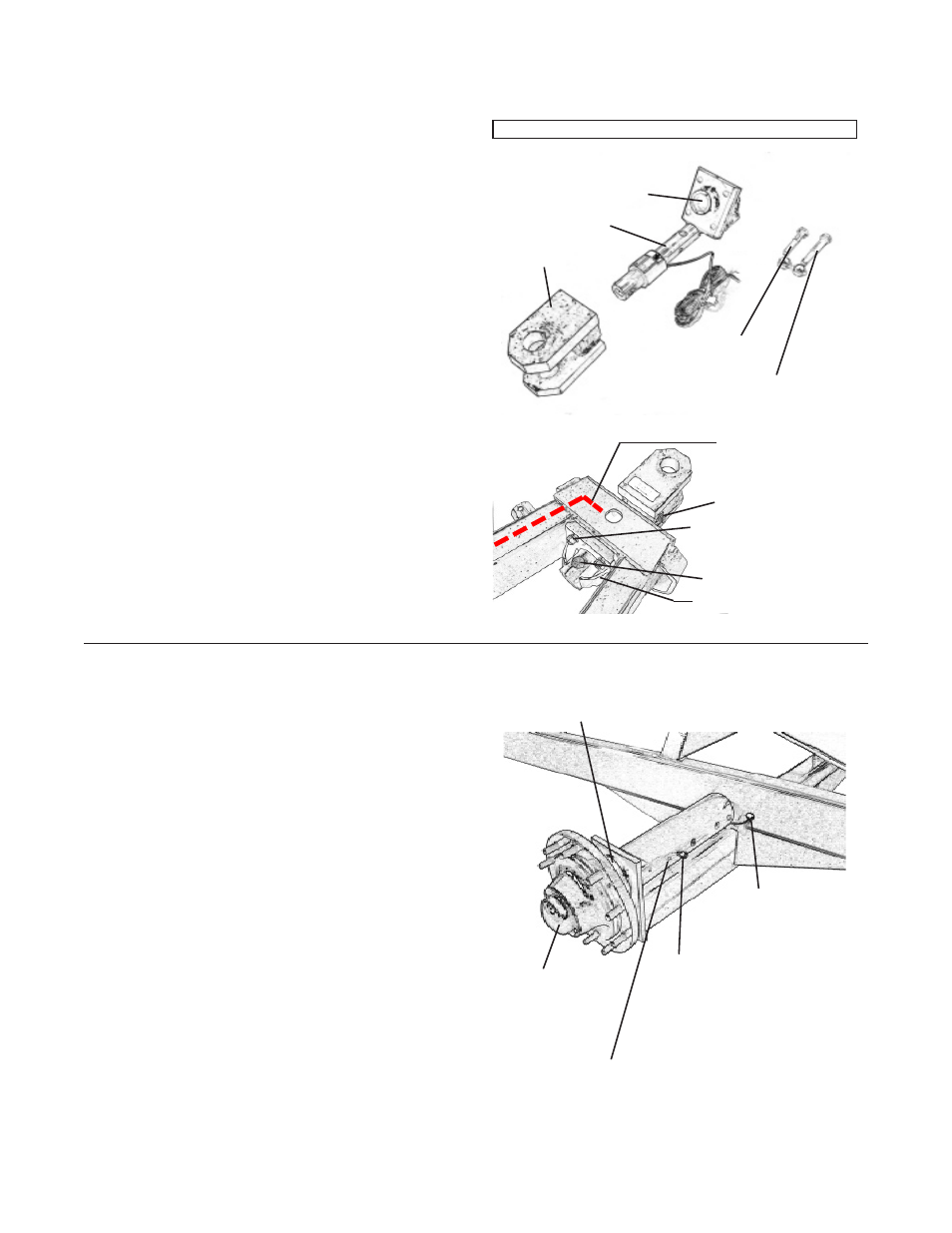
HITCH ASSEMBLY
1.
2.
3.
4.
5.
6.
Swivel Hitch
Weigh Bar
Weldment
1” x 4 1/2” Grade 5
Bolt with Lock Nut
Weigh Bar
1” x 5 1/2” Grade 5
Bolt with Lock Nut
HITCH PARTS
With the cart empty, place a 10-ton jack and jack
stands under the axle, near the tire to support the
weight of the grain cart.
Remove the wheel & tire and hub assembly from the
spindle. Remove the 1” x 7” hex bolt and lock nut
located on the stock end of the spindle. Slide the
spindle out from the A-Frame of the grain cart.
Run the wire on the weigh spindle through the tubing
of the A-Frame toward the front leg of the grain cart
where the Scale Indicator will be mounted. Insert
the Adapter Pipe Tubing and Weigh Spindle into the
cross axle frame of the grain cart and secure using
the 5/8” x 6 1/2” Grade 5 bolt and lock nut. Be sure
the weigh spindle is secured with the “TOP” decal
facing up.
Re-attach the hub to the weigh spindle. (Note: De-
pending on the model and year of grain cart, the seal
in the hub may also need to be changed.)
Attach the tire and wheel assembly. Be sure to
tighten the lug nuts to proper torque setting.
Repeat steps 1 through 5 for other side.
SPINDLE ASSEMBLY
1.
2.
3.
4.
5.
6.
3/4” x 3” Gr 8 Bolt
Weigh Bar Weldment
Run Wire from
Weigh Bar through
Left Side of A-Frame
Run spindle
wire through
grommet and
A-Frame to-
ward front leg
of grain cart.
Bolt Weigh
Spindle to
A-Frame
Axle here.
Be sure Weigh Spindle
is positioned with the
“TOP” facing upward.
Re-attach hub to
Weigh Spindle.
1” x 4 1/2” Gr 5 Bolt
1” x 5 1/2” Gr 5 Bolt
Installation of Scale System
for Single Wheel for Models 1000, 1050, 1051, 1150, 1151, 1325 or 1326
and Models 1325 or 1326 Equipped with Dual Wheels or Grain Carts Equipped with Tracks
Bolt 4 1/2” Diameter
Weigh Spindles Here