J&M TB-3500-6000A User Manual
Page 13
Pg. 13
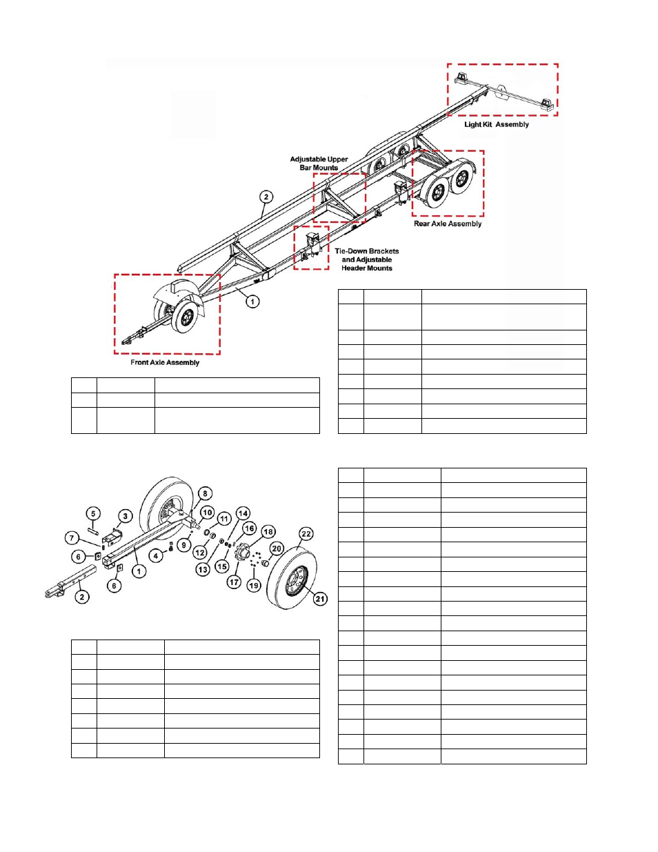
PARTS LIST
Main Frame and Upper Bar
Front Axle Assembly
#
Part #
Description
2
UB-24H
4" x 8" x 24' Upper Bar (takes two
plus splice plate to make 48' bar)
2
UB-42H
4" x 8" x 42' Upper Bar
2
UB-38H
4" x 8" x 38' Upper Bar
2
UB-32H
4” x 8” x 32’ Upper Bar
3
SP-24H
Splice Plate (2 pcs)
4
12312B
1/2” x 3 1/2” Bolt
5
12-W
1/2” Regular Washer
6
12-LN
1/2” Lock Nut
# Part
#
Description
1
HHMF2
Header Transport Main Frame
1
HHMF2L
Transport Main Frame (for units
equipped with 48' upper bar)
#
Part #
Description
8
124BG5
1/2” x 4” Grade 5 Bolt
9
12LN
1/2” Lock Nut
10 FS-HC1
Front
Spindle
11 27001500
Grease
Seal
12 25580
Large
Bearing
(0170012C)
13 104082
Small
Bearing
14 HC-SW
Spindle
Washer
15
SN-HC1
Slotted Spindle Nut
16 HC-CP
Cotter
Pin
17
3160333
Hub, 6 Bolt w/cups & studs
18 HCWS-1
Wheel
Stud
19 WN-HC1
Wheel
Nut
20 502019
Dust
Cap
21
WR-156-6HC
Wheel Rim, 15x6, 6 hole
21
WR-166-6HC
Wheel Rim, 16x6, 6 hole
22
ST225-75E
15” New Tire (TB-3500A)
22
ST235-85D
16” New Tire (TB-6000A)
23
25520
Large Race (not shown)
24
67010
Small Race (not shown)
# Part
#
Description
1 OT-HC
Outer
Tongue
Weldment
2 IT-610NS Inner
Tongue
Weldment
3 TL-610NS Tongue
Latch
4
78214-BS
7/8” x 2 1/4” Bolt with spacer
5
LS-610
Latch Shaft, 1” dia. x 5 3/4”
6 SB-212
Spacer
Blocks
7
SS-615NS
Small Spring in Latch