Input mode selections, Input mode selection jumpers, Voltage mode – AMX AXC-INP8 User Manual
Page 7: Switch mode
Input Mode Selections
3
AXC-INP8 Eight Switch/Opto-Logic Voltage Input Card
Input Mode Selections
Input Mode Selection Jumpers
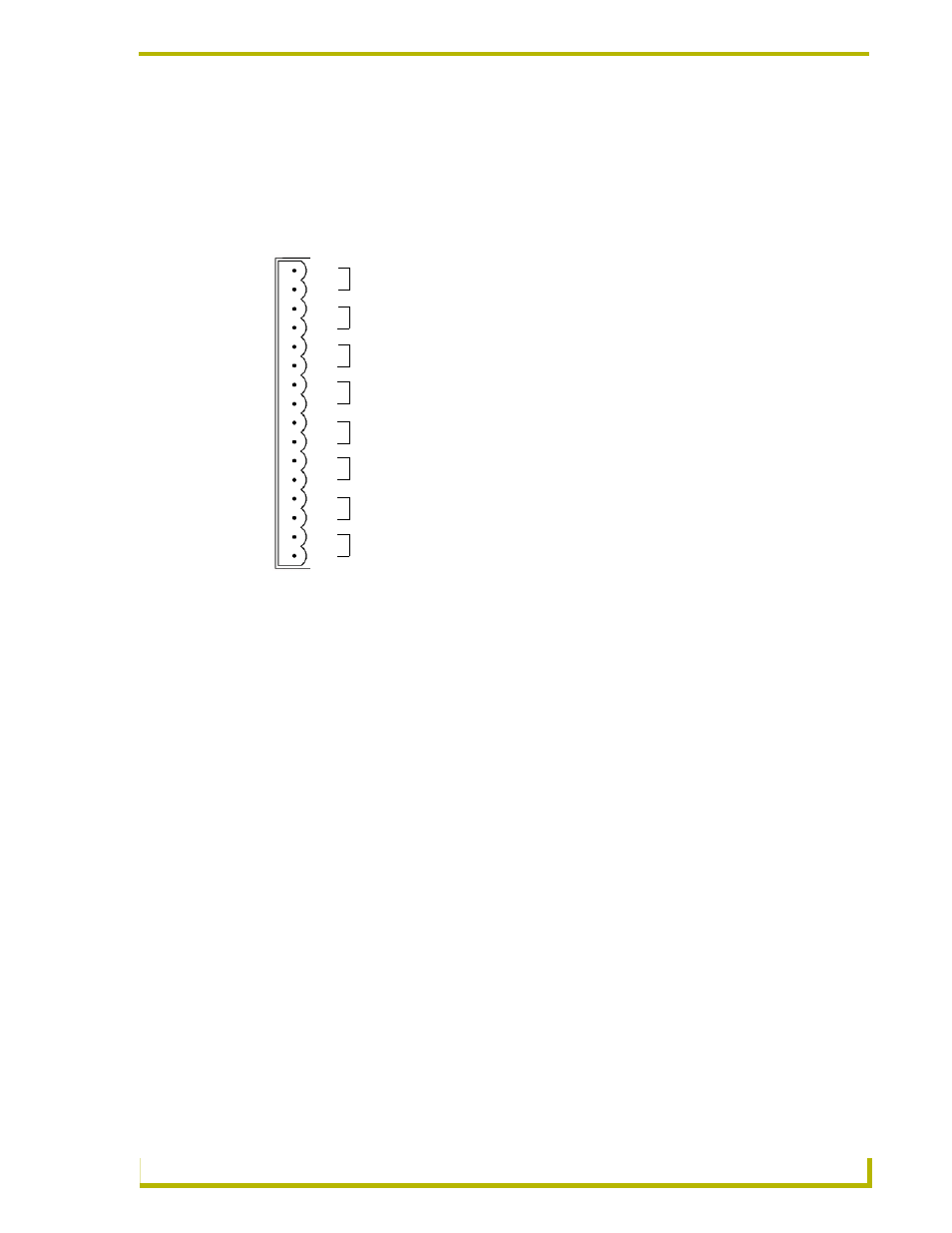
FIG. 1 shows the Input Mode selection jumpers.
Voltage Mode
Voltage Mode is used to sense high and low voltage states, commonly from AC or DC signals from
relay-controlled tape transports and LED feedback from preset dimming systems. This mode
provides opto-isolation.
The jumper for each input should be set in the VO position before wiring the input signal to the
card. An "on" (high) condition will be triggered by DC levels from 3.5 - 28 volts or an AC level
from 2.5 - 24 volts. The required current is 0.6 mA at 5 V or 1.6 mA at 12 V.
Switch Mode
Switch Mode is used to sense switch or relay contact closures. Inputs using the AMX PCS Power
Current Sensor will use this setting. Refer to the PCS and PCS2 Power Current Sensors instruction
manual for additional information.
The jumper should be set in the SW position. Note that the "A" terminal of all inputs in Switch
Mode shares the same common as the Axcess system ground. Sources that require isolation from
the system ground should use the voltage mode, with the installer providing switched DC power for
sensing, if required.
FIG. 1 Input Mode selection jumpers
A
B
A
B
A
B
A
B
A
B
A
B
A
B
A
B
1
2
3
4
5
6
7
8
9
10
11
12
13
14
15
16
Input 1
Input 2
Input 3
Input 4
Input 5
Input 6
Input 7
Input 8